VCG IN
connector.
The
VCG
Summing Amp is
an in-
verting amplifier
whose output voltage is used to
control
a positive current source
and
a
negative current
source.
For
symmetrical
output
waveforms, the currents from the
two current sources are equal and directly
proportional to
the voltage of the VCG
Summing
Amplifier
output.
The
Diode Gate, which is
controlled
by
the Hysteresis Switch,
is
used to
switch the positive current or the negative
current to the timing capacitor
selected
by
the
FREQ
HZ
+2.5V !
C
-2.5V
I
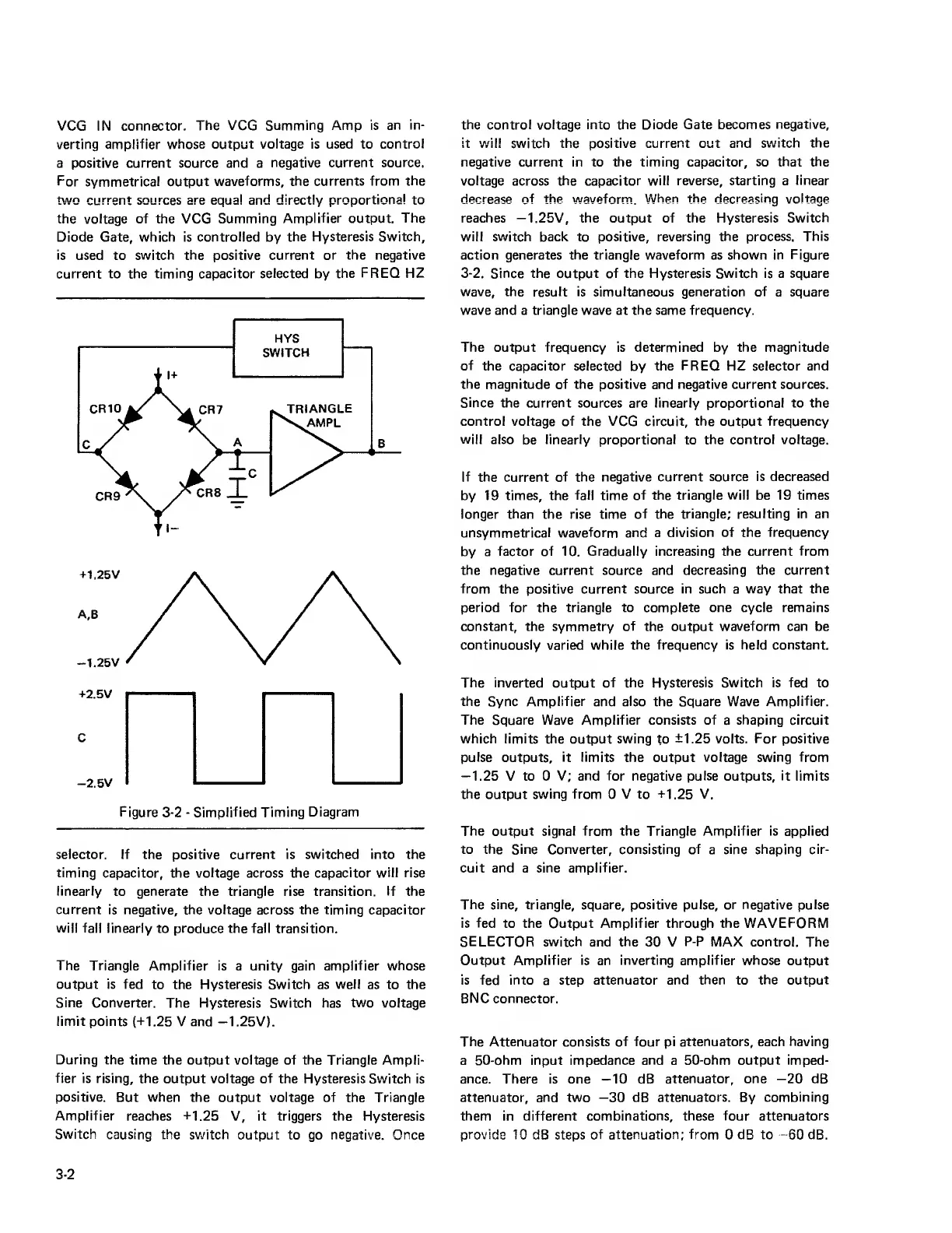
Figure
3-2
-
Simplified Timing
Diagram
selector. If the positive current is switched into the
timing
capacitor, the
voltage
across the
capacitor will rise
linearly
to generate the triangle rise transition. If the
current
is negative, the voltage across the timing capacitor
will fall
linearly
to
produce the fall transition.
The Triangle
Amplifier is a unity gain
amplifier whose
output is fed
to the Hysteresis Switch as
well
as to the
Sine
Converter. The Hysteresis Switch has two voltage
limit points
(-1-1.25
V and —1.25V).
During the
time the output voltage of the Triangle Ampli-
fier
is rising, the
output voltage
of
the Hysteresis Switch is
positive.
But
when
the output voltage of the Triangle
Amplifier
reaches
-1-1.25
V, it triggers the Hysteresis
Switch
causing the sv.'itch
output to
go
negative. Once
the control voltage into the Diode Gate becomes
negative,
it will switch the positive
current
out
and switch the
negative current in to the timing capacitor, so
that the
voltage
across
the capacitor will reverse, starting a
linear
decrease of the waveform.
When the decreasing voltage
reaches —1.25V, the output of the Hysteresis
Switch
will switch back to positive, reversing
the process. This
action generates the triangle waveform as shown in
Figure
3-2.
Since
the output of the Hysteresis Switch is a square
wave, the result is
simultaneous
generation
of a
square
wave and a triangle wave at the same frequency.
The output frequency is determined by the magnitude
of
the capacitor selected
by
the
FREQ
HZ selector and
the magnitude of the positive and negative current sources.
Since the current sources are linearly proportional to the
control voltage of the VCG circuit, the output frequency
will
also
be
linearly proportional
to
the control voltage.
If the
current
of the negative
current source is decreased
by 19 times, the
fall
time
of the triangle will be 19 times
longer than the rise time
of the triangle; resulting
in an
unsymmetrical
waveform and a
division of the frequency
by a
factor of 10. Gradually increasing the
current from
the
negative
current
source
and decreasing the current
from the
positive
current source in such
a
way that
the
period for the triangle to complete one cycle remains
constant, the symmetry
of
the output
waveform can
be
continuously varied while
the frequency is held constant.
The inverted
output
of the Hysteresis Switch is fed to
the
Sync
Amplifier
and
also
the Square Wave
Amplifier.
The Square Wave Amplifier consists of
a
shaping circuit
which limits the
output
swing to ±1.25 volts. For positive
pulse
outputs,
it limits
the output
voltage swing from
—1.25
V to 0
V; and for
negative
pulse
outputs, it limits
the
output
swing from
0
V to
+1.25
V.
The output signal from the Triangle Amplifier is applied
to the Sine Converter, consisting of
a
sine shaping cir-
cuit
and a sine
amplifier.
The sine, triangle, square, positive pulse, or negative pulse
is
fed
to the Output Amplifier through the WAVEFORM
SELECTOR switch and
the
30 V
P-P
MAX control. The
Output Amplifier is
an
inverting amplifier whose
output
is fed into a step attenuator and
then
to
the output
BNC connector.
The Attenuator consists of four pi attenuators, each
having
a 50-ohm input impedance
and
a
50-ohm output imped-
ance.
There is one
—10
dB
attenuator, one
—20
dB
attenuator, and two
—30
dB
attenuators.
By
combining
them in different
combinations, these four attenuators
provide 10
dB steps
of attenuation; from
0
dB to
-60
dB.
3-2
 Loading...

