SECTION
OPERATION
3.1 CONTROLS
AND CONNECTIONS
The generator
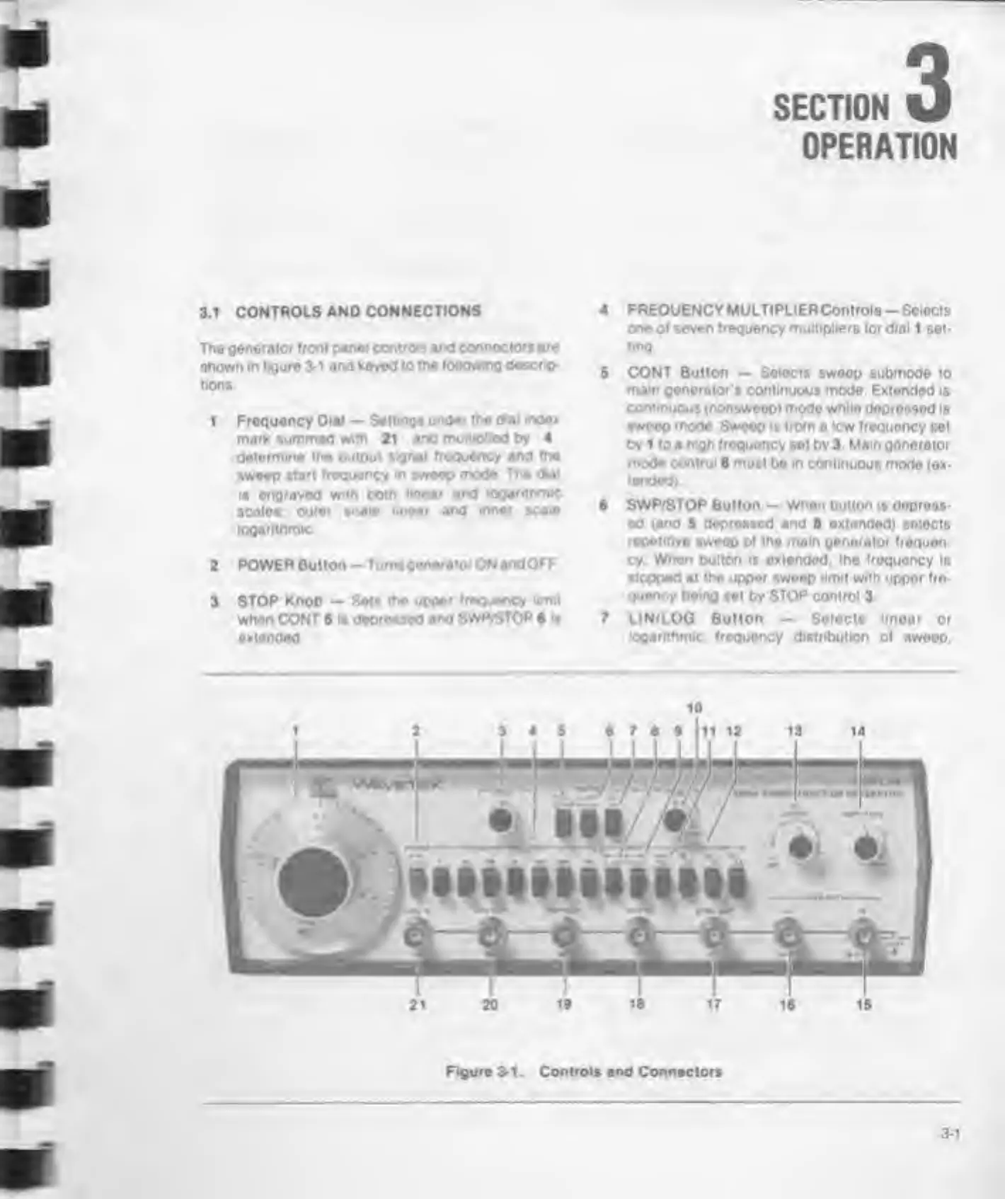
front panel controls and connectors
are
shown in
figure 3-1 and keyed
to
the following
descrip-
tions
1
Frequency Dial
—
Settings
unde* the d«ai index
mark summed
with
21
and multiplied by 4
determine the
output
signal frequency and
the
sweep
start frequency w sweep
mode The dial
Is engraved with both
linear and logarithms
scales
outer scale imear and
inner scale
logarithmic
2
POWER Button —
Tumsgonerator
ON
andOFF
3 STOP
Knob — Sets the upper
frequency limit
when CONT
5
Is depressed
and SWP/STOP
6
it
extended
4 FREQUENCY MULTIPLIERControls
-
Selects
one of seven frequency multipliers for dial 1 set-
ting.
5 CONT Button
—
Selects swoop
submode to
mam generator
s
continuous mode.
Extended is
continuous (nonsweep) mode while depressed
is
swoop
mode
Sweep is from a low frequency
set
by 1 to a
high frequency
set by 3 Mam generator
mode
control
8 must be in continuous
mode (ex-
tended)
6
SWP/STOP
Button
- When button
is
depress-
ed
(and
5
depressed
and 8 extended) selects
repetitive sweop of the main generator frequen-
cy When pulton is extended, the frequency is
stopped at the upper sweep
limit
with uppor fro-
Quoncy being
set by
STOP
control 3
7 LIN/LOG Button
—
Selects linear or
logarithmic frequency distribution
of sweep.
Figure 3-1. Controls and
Connectors
3-1