Connector Impedance
5
FUNCTION
12 Set to desired waveform.
500
OUT
(HI)
500
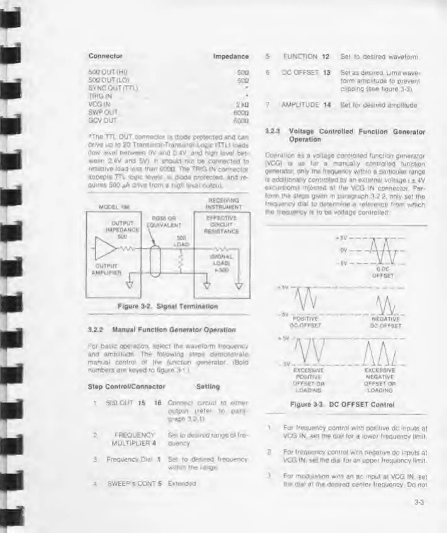
6 DC OFFSET 13
Set as
desired.
Limit wave-
500 OUT
(LO) 500 form amplitude
to
prevent
SYNC OUT (TTL)
•
clipping (see figure 3-3).
TRIGIN
•
VCG
IN
2kO 7 AMPLITUDE
14 Set for
desired
amplitude
SWPOUT
6000
GCVOUT
6000
•The TTl OUT connector is
dode
protected
ano can
drive
up to 20 Transistor-Transistor-Logic (TTL) loads
(low level between
OV
and
0
4V. and
high
level
bet-
ween 2.4
V
and
5V) It shooId not be connected to
resistive load less than
600Q
The TRIG IN connector
accepts TTL logic levels, is diode protected, and
re-
quires
500 j*A dnve from
a
n.gh level
output
RECEIVING
MOOEl IBS INSTRUMENT
OUTPUT
IMPEDANCE
ROM OR
EQUIVALENT
\
“
LOAD_
EFFECTIVE
CIRCUIT
RESISTANCE
OUTPUT
AMPl
IPIFR ,
r
<
(SIGNAL
LOAD!
P50U
muruiritn
f
V
1,
Figure 3-2. Signal Termination
3.2.2 Manual Function Generator Operation
For basic
operation, select the waveform frequency
and
amplitude The following
steps
demonstrate
manual control
o»
the (unction generator (Bold
numbers are keyed to
figure
3-1.)
Step Control/Connector Setting
3.2.3 Voltage
Controlled Function Generator
Operation
Operation
as a voltage controlled (unction
generator
(VCG) is
as
(or
a
manually
controlled (unction
generator,
only the frequency within
a
particular
range
»s add'tionaily controlled
by
an
external voltago
( ± 4V
excursions) mjocted
at
the
VCG IN connector. Per-
form
the steps given in paragraph
3.2
2.
only
set
tho
frequency dial
to determine
a
reference from
which
the frequency
is to be voltage controlled
HE
0 DC
OFFSET
POSITIVE
NEGATIVE
OC
OFFSET
DC OFFSET
:.W"TAT
EXCESSIVE
EXCESSIVE
POSITIVE NEGATIVE
OFFSET
OR OFFSET OR
LOADING
LOAOING
1 500 OUT 15 16
2
FREQUENCY
MULTIPLIER 4
3
Frequency Dial
1
4 SWEEP
S
CONT 5
Connect circuit to
either
output
(refer
to
para-
graph
3 21)
Set to
desired
range of fre-
quency
Set to
desired frequency
within the range
Extended
Figure 3-3.
DC
OFFSET
Control
1 For frequency control with
positive dc inputs
at
VCG IN.
set
the dial for
a
lower
frequency limit
2 For
frequency
control with negative
dc inputs at
VCG
IN.
set the dial for an upper frequency
limit.
3 For modulation with an
ac
input
at VCG IN.
set
the dial
at the desired center frequency.
Do not