12
D. Adjust the AMPL knob for the desired amplitude at the OUTPUT connector.
NOTE: For low level applications, pull the AMPL knob for -20 dB (10-to-1 reduction)
attenuation
of
the output signal.
E.
Pull and ad just the OFFSET knob for a
DC
offset
in
the output signal at the OUTPUT
connector. The signal duty cycle may be varied by rotating the DUTY knob. Pull
it
to
invert the dut y cycle.
F. There
is
a simultaneous output at the TTL/CMOS connector. This output will drive 1ogic
circuitry.
TIL
output leve! is fixed at >3
V.
For CMOS circuitry operating from a
5-to-15 volt power supply, pull the TTL/CMOS knob and adjust the leve! to the desired
value.
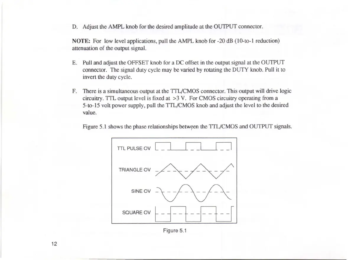
Figure
5.1
shows the phase relationships
betw~en
the TTL/CMOS and OUTPUT signais.
TIL
PULSE OV
TRIANGLE OV
_
SQUARE OV
Figure
5.1