148 CHAPTER 13 CLICK 200
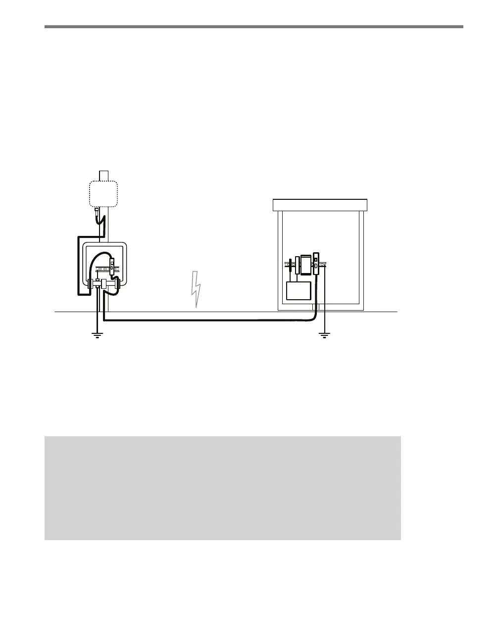
Follow the steps below to include surge protection using Click 200 devices (see Figure 13.3):
1 Install a Click 200 device in a pole-mount box on the same pole as the sensor being
protected.
2 Install another Click 200 in the main trac cabinet.
3 Connect the cable from the sensor to the PROTECTED side of the Click 200 in the
pole-mount cabinet. e SmartSensor cable should be kept as short as possible.
4 Connect a cable from the UNPROTECTED side of the Click 200 on the pole to the
UNPROTECTED side of the Click 200 in the main trac cabinet (see the section on
wiring for how to do this).
Smart
Sensor
120
VAC
Main Trac Cabinet
ac
Both ends of the homerun
cable connect to the
UNPROTECTED side of
the surge modules.
Figure 13.3 – Standard SmartSensor Installation Using Homerun Cable
Wiring the Cable
Figure 13.4 below shows how to wire the two sides of the Click 200. e UNPROTECTED
side of the Click 200 is not surge protected and is designed to be connected to the source(s)
from which power surges may come.
Note
It is important to note that there are two dierent cables that could be used with
the Click 200. All new SmartSensor HD and V sensors are sold with the 8-conductor
cable, so that’s what this lesson will discuss. Older installations, however, may still
have the 9-conductor cable, often just called the SmartSensor cable. Dierences in
the wiring of the 9-conductor cable are noted below.