CHAPTER 13 CLICK 200 149
If you have a 9-conductor cable, there is a ground (gray) wire and a total of three drains; these
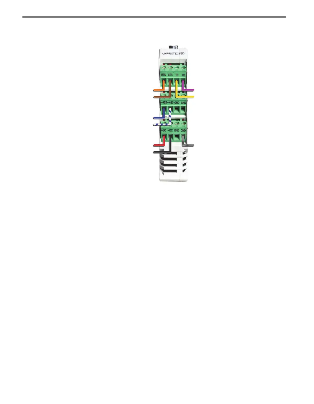
can all be wired into any of the GND terminals. Also, the +485 wire will not have a blue stripe.
-DC (Black)
+DC (Red)
+485 (White)
-485 (Blue)
CTS (Brown)
RTS (Orange)
Drain
TD (Yellow)
RD (Purple)
Figure 13.4 – Click 200 Terminal Connections
Wiring to Earth Ground
All Click 200 devices should be mounted on a DIN rail that is connected to earth ground,
either through an earth-grounded chassis or a 16 AWG or larger grounding wire attached to
a 7-foot grounding rod. Follow the steps below to correctly wire to earth ground:
1 Connect the grounding wire from either the DIN rail or a GND screw terminal on the
UNPROTECTED side of the Click 200 to the lug bolt on the inside of the pole-mount
box.
2 Connect another grounding wire from the exterior lug bolt to earth ground.
Verify Connections to Earth Ground
If there is not a good connection to ground, the Click 200 cards will not protect any equip-
ment. Aer all connections have been wired, verify that a good connection is made between
the Click 200 cards and earth ground by following the steps below:
1 Use a multimeter that is able to measure resistance in increments of less than one ohm.
2 Connect one probe to the drain on the unprotected side of the Click 200 (see Figure
13.5); connect the other probe on the multimeter to earth ground.