11
Please Do Not Return This Product To The Store. Contact your local Wayne-Dalton dealer. To find your local Wayne-Dalton dealer, refer to your
local yellow pages/business listings or go to the Find a Dealer section online at www.wayne-dalton.com
Tools Needed:
INSTALLATION
Installation
1
IMPORTANT: READ INSTRUCTIONS TITLED “P4” “REMOVING THE OLD DOOR” ON PAGE 9 AND “P5” “PREPARING THE OPENING” ON
PAGE 10 BEFORE ATTEMPTING DOOR INSTALLATION.
IMPORTANT: STAINLESS STEEL OR PT 2000 COATED LAG SCREWS MUST BE USED WHEN INSTALLING CENTER BEARING BRACKETS,
END BRACKETS, JAMB BRACKETS, OPERATOR MOUNTING/SUPPORT BRACKETS AND DISCONNECT BRACKETS ON TREATED LUMBER
(PRESERVATIVE-TREATED). STAINLESS STEEL LAG SCREWS ARE NOT NECESSARY WHEN INSTALLING PRODUCTS ON UNTREATED
LUMBER.
NOTE: It is recommended that 5/16” x 2” lag screws be pilot drilled using a 3/16” drill bit, and 1/4” x 2” lag screws and 1/4” x 1-1/2”
lag screws be pilot drilled using a 1/8” drill bit, prior to fastening.
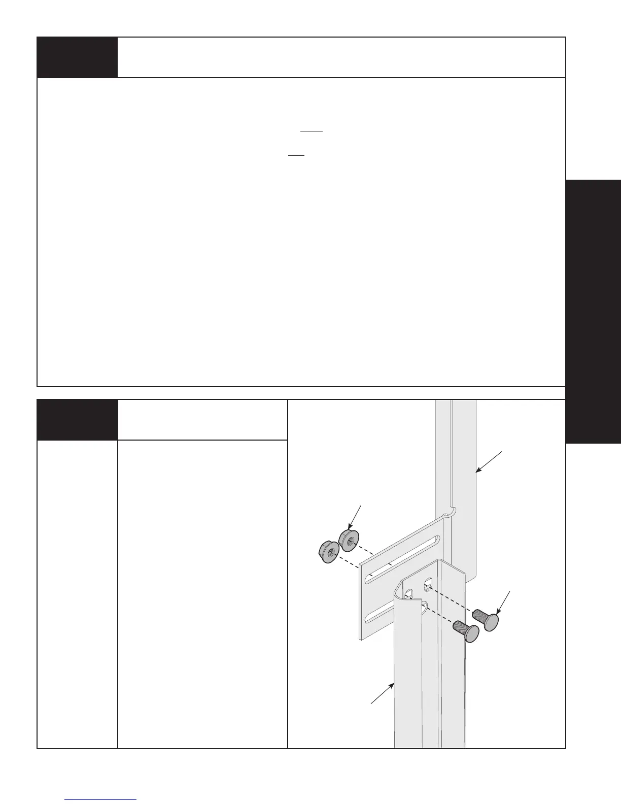
Attaching Fully Adjustable
Flagangle to Vertical Track
None
NOTE: If you have riveted track, skip
this step.
Hand tighten the flagangle to the
vertical track using (2) 1/4”- 20 x 5/8”
carriage bolts and (2) 1/4”- 20 flange
hex nuts. Secure the flange nuts after
flagangle spacing is complete (Step 12).
(2) 1/4”- 20 X 5/8”
CARRIAGE BOLTS
(2) 1/4”- 20
FLANGE HEX NUTS
FULLY
ADJUSTABLE
FLAGANGLE
VERTICAL
TRACK