NOTE: Install the 5/16” - 18 x 1/2” carriage bolts and the 5/16” - 18 flange hex nuts as far
apart as possible, prior to securing both top and bottom halves together.
Now, locate the center of the top section and align the center of the holes in the drawbar op-
erator bracket assembly with the top section center line. Align the drawbar operator bracket
assembly vertically.
NOTE: For retro fit applications, the drawbar operator bracket assembly must be aligned with
an existing operator.
Slide the top halve of the drawbar operator bracket assembly under the strut, keeping the
drawbar operator bracket assembly aligned with the center line. Remove the strut’s screws, if
necessary and attach to the top section (through strut if necessary) using (3) 1/4” - 20 x 7/8"
self drilling screws.
NOTE: If your door lacks a strut on the top section, ignore the previous paragraph.
Attach the bottom halve of the drawbar operator bracket to the section surface using (3) 1/4”
- 20 x 7/8” self drilling screws.
NOTE: When attaching drawbar operator bracket to top section with strut, apply additional
pressure to thread into the strut.
(3) 1/4”- 20 x 7/8”
Self-drilling screws
(4) 5/16”- 18 x 1/2”
Carriage bolts and
(4) 5/16”- 18 flange
hex nuts
(3) 1/4” -20 x 7/8”
Self-drilling screws
Bottom half
Top half
Strut
Drawbar
operator bracket
Locate the center of the top section. Position the drawbar operator bracket under the strut
(if applicable) or align the drawbar operator bracket top edge with the top edge of the top
section, as shown. Attach the drawbar operator bracket using (3) 1/4” - 20 x 7/8” self-drilling
screws (as shown).
(3) 1/4”- 20 x 7/8”
Self-drilling screws
Pin
stripes
Top section
Strut
Drawbar
operator
bracket
Attaching Horizontal Tracks
14
NOTE: Depending on your door, you may have Quick Install Flag Angles, Fully Adjustable Flag
Angles, Riveted Vertical Track Assemblies or you may have Angle Mount Vertical Track As-
semblies. Refer to Package Contents / Breakdown of Parts, to determine which Flag Angles /
Vertical Track Assemblies you have.
WARNING
DO NOT RAISE DOOR UNTIL HORIZONTAL TRACKS ARE SECURED AT
REAR, AS OUTLINED IN STEP, REAR BACK HANGS, OR DOOR COULD FALL
FROM OVERHEAD POSITION CAUSING SEVERE OR FATAL INJURY.
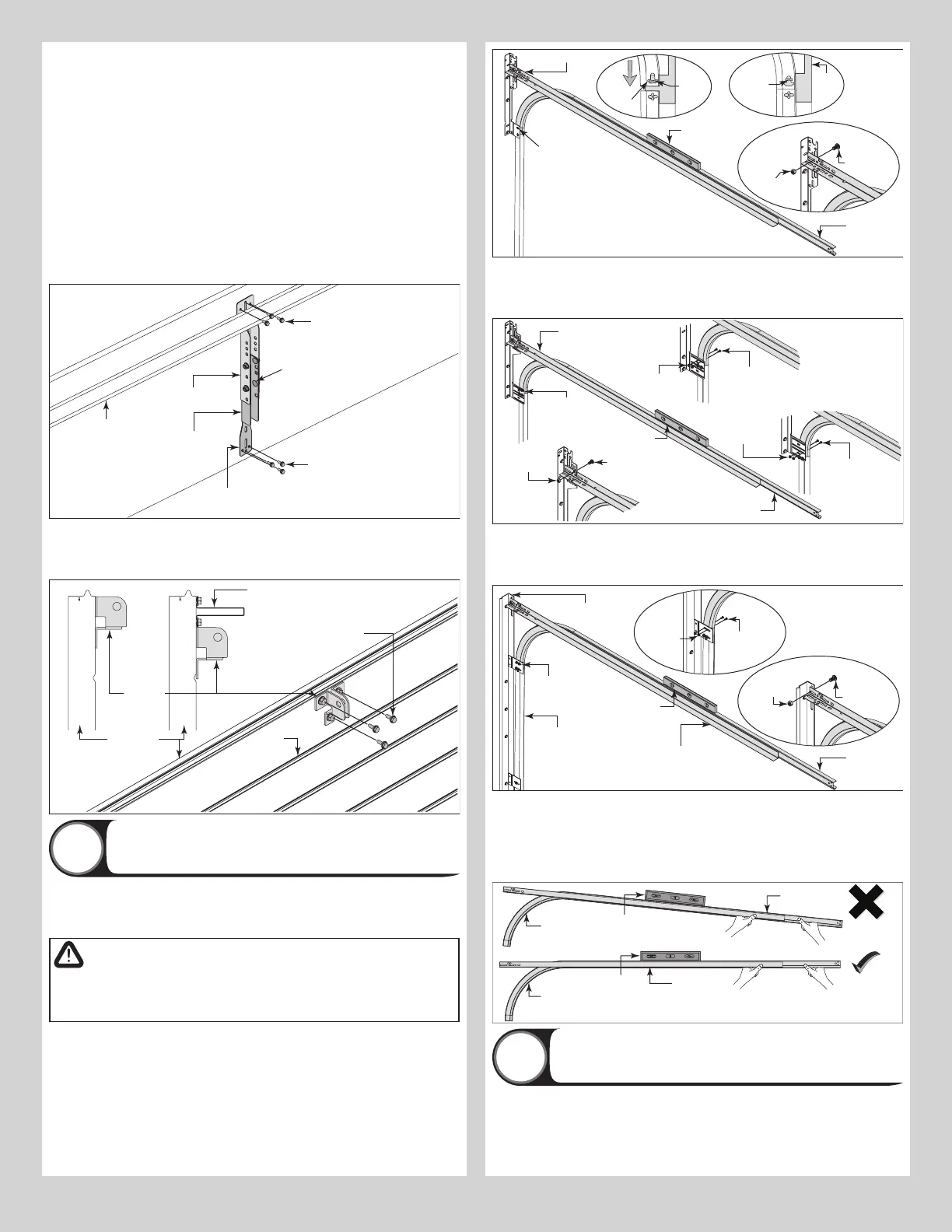
IF YOU HAVE QUICK INSTALL FLAG ANGLES: To install horizontal track, place the curved
end over the top track roller of the top section. Align key slot of the horizontal track with the
Quick Install tab of the flag angle. Push curved portion of horizontal track down to lock in
place.
3/8”-16
Hex nut
3/8”-16 x
3/4” Truss
head bolt
Quick
Install
tab
Key
slot
Quick
Install
tab in
place
Level
Horizontal track angle
Flag
angle
upper
slot
Flag
angle
Horizontal
track
FOR OTHER FLAG ANGLES: To install horizontal track, place the curved end over the top
track roller of the top section. Align the bottom of the horizontal track with the top of the verti-
cal track. Tighten the horizontal track to the flag angle with (2) 1/4” - 20 x 9/16” track bolts
and (2) 1/4” - 20 flange hex nuts.
3/8”-16
Hex nut
Horizontal
track angle
3/8”-16 x 3/4”
Truss head bolt
1/4”-20 x 9/16”
Track bolts
1/4”-20 Flange
hex nuts
Horizontal
track
Flag angle
upper slot
Level
1/4”-20 x 9/16”
Track bolts
1/4”-20 Flange
hex nuts
12” Radius
track
15” Radius track
IF YOU HAVE ANGLE MOUNT: To install horizontal track, place the curved end over the
top track roller of the top section. Align the bottom of the horizontal track with the top of the
vertical track. Tighten the horizontal track to the angle mount with (2) 1/4” - 20 x 9/16” track
bolts and (2) 1/4” - 20 flange hex nuts.
3/8”-16
Hex nut
Angle
mount
3/8”-16 x
3/4” Truss
head bolt
1/4”-20 x
9/16”
Track bolts
1/4”-20
Flange
hex nuts
Horizontal
track
Upper slot
Level
Vertical
track
Horizontal
track angle
Next level the horizontal track assembly and bolt the horizontal track angle to the first
encountered slot in the flag angle / angle mount using (1) 3/8” - 16 x 3/4” truss head bolt
and (1) 3/8” - 16 hex nut. Repeat for other side. Remove nail that was temporally holding the
top section in position.
IMPORTANT: FAILURE TO REMOVE NAIL BEFORE ATTEMPTING TO RAISE DOOR COULD
CAUSE PERMANENT DAMAGE TO TOP SECTION.
Horizontal
track
Level
Level
Horizontal
track angle
Horizontal
track angle
Horizontal
track
Adjusting Top Fixtures
15
With horizontal tracks installed, you can now adjust the top fixtures. Vertically align the top
section of the door with the lower sections. Once aligned, position the top fixture slide, out
against the horizontal track. Maintaining the slide’s position, tighten the (2) 1/4” - 20 flange
hex nuts to secure the top fixture slide to the top fixture base. Repeat for other side.
10