manual to determine what size sections you need to use as your lock (second) section, inter-
mediate (third) section, intermediate (fourth) section and top section. Measure your sections
to make sure they are the correct height as indicated on the chart.
NOTE: The graduated end and center hinges can be identified by the number stamped onto
their lower hinge leaf.
NOTE: The #1, #2, #3, #4, graduated end hinges (Wide body) serves as end hinges on all
sections, except for the top section.
NOTE: The #1 Center hinge(s) (Narrow body) serves as center hinges on all sections, except
for the top section.
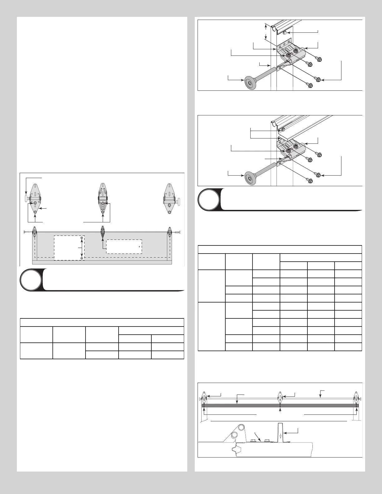
Starting on the left hand side of the bottom section, align the lower hinge leaf of the #1
graduated end hinge (wide body) over the holes, located at the top of the end caps. Align the
lower hinge leafs of the #1 center hinges (narrow body) with the pre-marked locations at the
center locations at the top of the section. Attach the lower hinge leafs to the section using (2)
1/4” - 14 x 7/8” self drilling screws.
IMPORTANT: ONCE THE 1/4” - 14 X 7/8” SELF DRILLING SCREWS ARE SNUG AGAINST THE
LOWER HINGE LEAFS, TIGHTEN AN ADDITIONAL 1/4 TO 1/2 TURN TO RECEIVE MAXIMUM
DESIGN HOLDING POWER.
Place a short stem track roller into each graduated end hinge. Repeat graduated hinge
attachment using the appropriate graduated end hinges for all remaining sections except the
top section.
IMPORTANT: WHEN PLACING SHORT STEM TRACK ROLLERS INTO THE #2 GRADUATED
END HINGES AND HIGHER, THE SHORT STEM TRACK ROLLER GOES INTO HINGE TUBE
FURTHEST AWAY FROM SECTION.
NOTE: The #2 graduated end hinges serves as end hinges on the Lock section.
NOTE: The #3 graduated end hinges serves as end hinges on the Intermediate I section.
NOTE: The #4 graduated end hinges serves as end hinges on the Intermediate II section.
#1Center hinge(s)
(Narrow body)
#1 Graduated end
hinge (Wide body)
Lower leaf
#2 Graduated end hinge
(roller inserted into tube
furthest from section)
(2) 1/4”-14 x 7/8” Self
drilling screw locations
Pre-punched
holes in
endstiles
Pre-marked
location(s) on
section surface
Short stem
track roller
Attaching Top Fixtures To Top Section
5
NOTE: Refer to door section identification, located in the pre-installation section of this
manual to determine what size sections you need to use as your top section.
NOTE: Refer to the strutting schedule below to determine the top section requires a strut. If
your top section is not noted in the strutting schedule, it doesn’t require a strut.
Top Section Strutting Schedule
Section
Quantity
Section Type Solid / Win-
dows
Door Widths
6’0” - 10’0” 12’0” - 18’0”
4 - 8 Top Solid - 2”
Windows 2” 2”
Starting on the left hand side, align the top fixture base 3” down from the top section or
below strut and even with the edge of the top section. The slotted half of the top fixture base
should be facing upwards. Fasten to section through end cap using (4) 1/4” - 14 x 7/8” self
drilling screws. Insert short stem track roller into top fixture slide. Repeat for other side.
NOTE: The top fixture slide will be tightened and adjusted later, in step, Adjusting Top Fixture.
NOTE: Ensure the top fixture slide is able to slide along the top fixture base. If needed, loosen
the 1/4” - 20 flange hex nuts.
IMPORTANT: IF NO STRUT WAS INSTALLED ON THE TOP SECTION, PLACE (1) 1/4” - 14 X
7/8” SELF DRILLING SCREW INTO THE TOP PRE-PUNCHED HOLE IN EACH ENDSTILE OF THE
TOP SECTION.
(4) 1/4”-14 x 7/8”
Self drilling screws
Top fixture
base
End cap
Top fixture slide
Top section
(2) 1/4”-20
Flange hex nuts
Insert short
stem track roller
1/4”-14 x 7/8”
Self drilling screw
3”
Place the strut on the top section, center the strut side to side on the top edge of the top
section. Secure to the section using (2) 1/4” - 14 x 7/8” self drilling screws at each endstile
and (2) 1/4” - 14 x 7/8” self drilling screw at each center hinge location at each pre-marked
location.
(4) 1/4”-14 x 7/8”
Self drilling screws
Top fixture
base
End cap
Top fixture slide
Top section
(2) 1/4”-20
Flange hex nuts
Strut
Insert short
stem track roller
(2) 1/4”-14 x 7/8”
Self drilling screws
Attaching Struts
6
NOTE: Depending on the size of your door, one or more sections may require a strut.
Using sawhorses, lay section on a flat smooth surface. Referring to the strutting schedule
below, to determine how many struts your door needs and on what sections they are needed
to be installed.
NOTE: Sections not noted in the strutting schedule, do not require a strut.
Bottom, Lock, Intermediate(s) section Strutting Schedule
Section
Quantity
Section Type Solid /
Windows
Door Width
6’0” - 10’0” 12’0” 13’0” - 18’0”
4 Intermediate I Solid - - -
Windows 2” 2” -
Lock Solid - - -
Bottom Solid - - 2”
5 Intermediate II Solid - - -
Windows 2” 2” -
Intermediate I Solid - - 2”
Windows 2” 2” 2”
Lock Solid - - -
Bottom Solid - - 2”
NOTE: All strut(s) are placed at the top of the section.
Place the strut on the section up against the bottom of the hinges. Center the strut side to
side on the section as shown. Secure to the section using (2) 1/4” - 14 x 7/8” self drilling
screws at each end hinge location and (2) 1/4” - 14 x 7/8” self drilling screw at each center
hinge location.
Typical
section
Strut
Lower
hinge leaf
1/4”-14 x 7/8” Self drilling
screws
Graduated
end hinges
hinge(s)
Strut
Top portion
of section
7