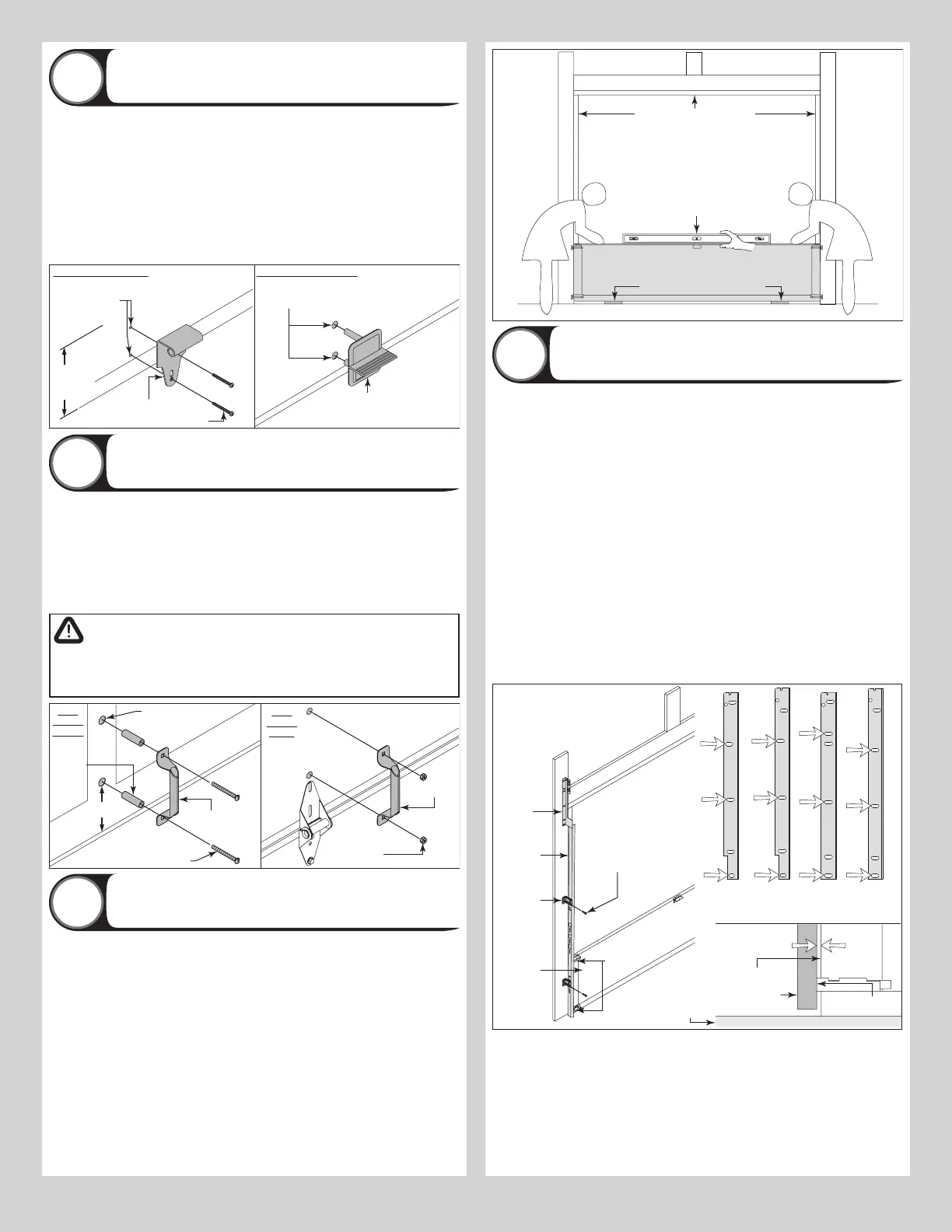
Attaching Step Plate To Bottom Section
7
On the inside of the bottom section, locate the vertical center of the door. Center the inside
step plate vertically no higher than 8” from the bottom of the door to the top of the step plate.
IMPORTANT: DO NOT MOUNT THE STEP PLATE HIGHER THAN 8” FROM THE BOTTOM OF
THE SECTION.
Using the inside step plate’s second top most hole and bottom hole as a template, drill 7/16”
diameter holes through the entire section.
IMPORTANT: BE EXTREMELY CAREFUL TO KEEP DRILL STRAIGHT.
Now insert the outside step plate into the holes through the front of the door, mounting the
two step plates back to back. Secure step plates together with two No. 8 screws through the
inside step plate and into the outside step plate.
Inside step plate
(2) #8 Screws
8” Max.
mounting
height
Outside
step plate
7/16”
Diameter holes
Drill (1) 7/16”
diameter hole
at each marked
location
Attaching Lift Handles
8
Locate the vertical center of the lock (second) section of the door and position the lift
handle’s bottom hole 4” from the bottom of the lock section along the vertical center on the
outside of the door. Use the holes in the lift handle as a template to mark the hole locations.
IMPORTANT: THE LIFT HANDLE AND THE STEP PLATE NEED TO BE VERTICALLY ALIGNED.
Drill 9/32” diameter holes through the section at each marked location. Enlarge the holes
from outside the door to 1/2” diameter through the section. Assemble the outside and inside
lift handles to the section using (2) 1/4” - 20 x 2-1/2” carriage bolts and (2) 1/4” - 20 hex
nuts and spacers.
WARNING
TO AVOID POSSIBLE INJURY, LIFT HANDLES THAT ARE INSTALLED
WITHIN 4 INCHES (102MM) OF A SECTION INTERFACE SHALL PROMOTE
VERTICAL ORIENTATION OF THE HAND.
holes
4”
(2)
Spacers
(2) 1/4”-20 x 2-1/2”
Carriage bolts
section
outside
section
inside
(2) 1/4”-20
Hex nuts
Lift handle
Positioning Bottom Section
9
Center the bottom section in the door opening. Level the section using wooden shims (if
necessary) under the bottom section. When the bottom section is leveled, temporarily hold it
in place by driving a nail into the jamb and bending it over the edge of the bottom section on
both sides.
Weather seal (If applicable)
Level
Bottom section
Wooden shims (If necessary)
Attaching Vertical Tracks To Jambs
10
NOTE: Depending on your door, you may have Quick Install Flag Angles, Fully Adjustable Flag
Angles, Riveted Vertical Track Assemblies or you may have Angle Mount Vertical Track As-
semblies. Refer to Package Contents / Breakdown of Parts, to determine which Flag Angles /
Vertical Track Assemblies you have.
IMPORTANT: IF YOUR DOOR IS TO BE INSTALLED PRIOR TO A FINISHING CONSTRUCTION
OF THE BUILDING’S FLOOR, THE VERTICAL TRACKS AND THE DOOR BOTTOM SECTION
ASSEMBLY SHOULD BE INSTALLED SUCH THAT WHEN THE FLOOR IS CONSTRUCTED, NO
DOOR OR TRACK PARTS ARE TRAPPED IN THE FLOOR CONSTRUCTION.
IMPORTANT: THE TOPS OF THE VERTICAL TRACKS MUST BE LEVEL FROM SIDE TO SIDE.
IF THE BOTTOM SECTION WAS SHIMMED TO LEVEL IT, THE VERTICAL TRACK ON THE
SHIMMED SIDE MUST BE RAISED THE HEIGHT OF THE SHIM.
NOTE: Make sure the counterbalance lift cable is located between the track rollers and the
door jamb.
Starting on the left hand side of the bottom section, remove the nail. Position the left hand
vertical track assembly over the track rollers of the bottom section and install, as shown. Drill
3/16” pilot holes into the door jamb for the lag screws.
FOR QUICK INSTALL FLAG ANGLES OR FULLY ADJUSTABLE FLAG ANGLES: Loosely
fasten jamb brackets and flag angle to the jamb using 5/16” x 1-5/8” lag screws. Tighten lag
screws, securing the bottom jamb bracket to jamb, maintain 3/8” to 5/8” spacing, between
the bottom section and vertical track. Hang counterbalance lift cable over flag angle. Repeat
same process for other side.
Vertical
track
assembly
Jamb
bracket
Flag
angle
Flag angle lag screw locations
5/16” x 1-5/8”
Lag screws
Bottom
section
Track
rollers
12R FA
3/8” to 5/8”
Spacing
Bottom section
15R QI12R QI
Floor
Track roller
15R FA
Vertical track
FOR RIVETED VERTICAL TRACK ASSEMBLY: Loosely fasten jamb brackets and flag angle
to the jamb using 5/16” x 1-5/8” lag screws. Tighten lag screws, securing the bottom jamb
bracket to jamb, maintain 3/8” to 5/8” spacing as shown between the bottom section and
vertical track. Hang counterbalance lift cable over flag angle. Repeat same process for other
side.
FOR ANGLE MOUNT VERTICAL TRACK ASSEMBLY: Loosely fasten the slots in the wall
angle to the jamb using 5/16” x 1-5/8” lag screws. Tighten lag screws, securing the bottom
slot in the wall angle, maintain 3/8” to 5/8” spacing as shown between the bottom section
and vertical track. Hang counterbalance lift cable over angle mount. Repeat same process for
other side.
8