7
Cable Drum
No space between Ratchet
Pawl and Cable Drum
indicates engagem
ent
Cable Drum
Ratch
et Pawl
ENGAGED SID
E VIEW
No space between
Ratchet Pawl and
Cable Drum
ENGAGED UNDERNEATH VIEW
Space between Ratchet Pawl
and Cable Drum
non-indicates engagement
Cable Drum
Ratchet Pawl
DISENGAGED SIDE VIEW
No space between
Ratchet Pawl and
DISENGAGED U
NDERNEATH VIEW
UPPER POSITION
LOWER POSITION
LOWER POSITION SIDE VIEW
UPPER POSITION SIDE VIEW
Ratchet Pawl in Lower Position
Ratchet Pawl in Upper Position
Use these Illustr
ation, in conjunction with the Ins
tructions on the other side of
this label.
WA
Rachet B
E
XTREME
SPRING
TENSION
.
To avoid po
ssible severe or
fatal injury
,
DO
NOT
remove
fasteners from ratchet
bracket
until spring(s
) are fully
wnwou
nd.
To safely unwind spring(s)
read
and fol
low the directions i
n the
installation ins
tructions/owne
rs
manual
.
DO NOT REMOVE T
HIS TAG.
Cab
le Drum
No s
pace betwe
en Ratchet
Pawl and C
able Dr
um
indicates engagem
ent
Cable Drum
Ratchet Paw
l
ENG
AGED
SIDE VIEW
No s
p
Rat
che
Cabl
ENGAGED UNDERNEA
TH V
IEW
Space b
etween Ratche
t Pawl
and Cab
le D
rum
non-indicates engagem
ent
Cab
le Drum
Ratchet Paw
l
DISENGA
GED
SIDE VIEW
No s
pa
Ratche
DISENGA
GED U
NDERNEAT
H
UPPER
POSI
TIO
N
LOW
ER POSITION
LOW
ER POSITION
SIDE VIEW
UPPER POSI
T
ION
SIDE VIEW
Ratchet Paw
l in Lower
Position
Ratchet Pawl
in U
ppe
Use t
hese I
llus
tration, i
n c
onjunction with the Instructions on the other side of
this label.
Rac
het Bracket is under
EXTREME SPRING
TENSION
.
To
fatal in
jury,
DO NOT
remove
fasteners from ratchet bracket
unti
l spring(s) are fully
wnwo
und.
To
sa
fely unwind spring(s)
read
and fol
low the directions in the
inst
allation instructions/owners
manual.
DO NO
Cable Drum
No space between Ratchet
Pawl and Cable Drum
indicates engagement
Cable Drum
Ratchet Pawl
ENGAGED SIDE VIEW
No space between
Ratchet Pawl and
Cable Drum
ENGAGED UNDERNEATH VIEW
Space between Ratchet Pawl
and Cable Drum
non-indicates engagement
Cable Drum
Ratchet Pawl
DISENGAGED SIDE VIEW
No space between
Ratchet Pawl and
DISENGAGED U
NDERNEATH VIEW
UPPER POSITION
LOWER POSITION
LOWER POSITION SIDE VIEW
UPPER POSITION SIDE VIEW
Ratchet Pawl in Lower Position
Ratchet Pawl in Upper Position
Use these Illustration, in conjunction with the Instructions on the other side of
this label.
WARNING
Rachet Bracket is under
EXTREME SPRING
TENSION
.
To avoid possible severe or
fatal injury,
DO NOT
remove
fasteners from ratchet bracket
until spring(s) are fully
wnwound.
To safely unwind spring(s)
read
and follow the directions in the
installation instructions/owners
manual.
DO NOT REMOVE THIS TAG.
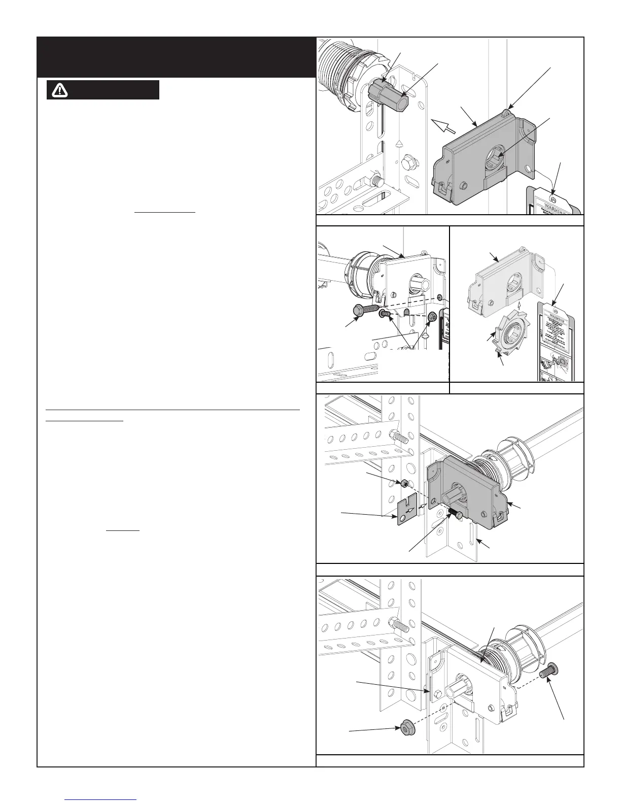
Splines
Winding
Shaft
Groove
Disconnect
Cable Guide Hole
Right End
Bracket
Warning
Tag
Right End
Bracket
Ratchet Wheel
Teeth
Pointing
Upward
5/16” x 1-5/8”
Hex Head Lag
5/16” - 18 x 3/4”
Carriage Bolt And
Hex Nut
Right End
Bracket
Warning
Tag
IT IS RECOMMENDED THAT LEATHER GLOVES BE WORN
WHILE WINDING THE TORQUEMASTER
®
PLUS SPRINGS.
FAILURE TO WEAR GLOVES MAY CAUSE INJURY TO
HANDS.
Starting with the right hand side, place a mark on winding shaft (or 5/8”
socket) and end bracket. Turn the pawl knob on the end bracket to the upper
position. Using a ratchet wrench with a 5/8“ socket, wind the spring by
rotating the winding shaft counter clockwise, while watching the mark on the
winding shaft, as shown in Fig. 3.6.
NOTE: A 3” extension is recommended to provide added clearance from the
horizontal angle, as shown in Fig. 3.6.
IMPORTANT: PAWL KNOB MUST BE IN UPPER POSITION TO ADD / REMOVE
REQUIRED NUMBER OF SPRING TURNS, AS SHOWN IN FIG. 3.9.
After 2-3 turns, remove the ratchet wrench and adjust the cable on the left
side, to ensure the cable is in the first groove of the cable drum.
NOTE: Single spring applications require no spring winding on the left hand
side, but does require cable adjustment.
IMPORTANT: COUNTERBALANCE CABLE TENSION MUST BE EQUAL ON BOTH
SIDES PRIOR TO FULLY WINDING SPRINGS.
SEE THE SPRING TURN CHART FOR THE REQUIRED NUMBER OF TURNS,
AS SHOWN IN FIG. 3.7
For single spring applications:
Return to the right hand and continue winding the spring to the required
number of turns for your door. Place pawl knob in lower position, as shown
in Fig. 4.0.
For double spring applications:
Place a mark on the winding shaft and end bracket. Place the ratchet with
5/8” socket onto the left hand winding shaft end. To wind the spring, rotate
the winding shaft clockwise, while watching the mark on the winding shaft.
Rotate the winding shaft to the required number of turns for your door.
Then return to the right hand side and wind the right hand spring to the
required number of turns. Place pawl knob in lower position on both sides, as
shown in Fig. 4.0.
IMPORTANT: MARK NUMBER OF SPRING TURNS ON TORQUEMASTER
®
PLUS
END BRACKET WARNING TAG(S), as shown in Fig. 3.8.
NOTE: Since total turns to balance door may deviate from SPRING TURN
CHART values by ± 1/2 turn, adjustments to the recommended number of
turns may be necessary.
IMPORTANT! HOLD THE DOOR DOWN TO PREVENT IT FROM RAISING
UNEXPECTEDLY IN THE EVENT THE SPRING WAS OVERWOUND AND
CAUTIOUSLY REMOVE VICE CLAMPS FROM VERTICAL TRACKS.
TorqueMaster
®
Plus Single and Double Spring Replacement
- Continued
FIG. 3.1
FIG. 3.3
FIG. 3.4
FIG. 3.5
Torquemaster
®
End
Bracket
1/4” - 20 Flange
Hex Nut
1/4” - 20 x 9/16”
Track Bolt
Torquemaster
®
Shim
5/16” - 18
Hex Nut
5/16” - 18 x 1”
Hex Head Bolt
Adapter Bracket
Torquemaster
®
End Bracket
Torquemaster
®
Shim
FIG. 3.2
WARNING
 Loading...