8
No space between Ratchet
Pawl and Cable Drum
indicates engagement
Cable Drum
Ratchet Pawl
ENGAGED SIDE VIEW
No space b
etween
Ratchet Pawl and
Cable Drum
ENGAGED UNDERNEATH VIEW
Space b
etween Ratchet Pawl
and Cable Drum
non-indicates engagement
Cable Drum
Ratchet Pawl
DISENGAGED SIDE VIEW
No space between
Ratchet Pawl and
DISENGAGED U
NDE
RNEATH VIEW
UPPER POSITION
LOWER POSITION
LOWER POSITION SIDE VIEW
UPPER POSITION SIDE VIEW
Ratchet Pawl in Lower Position
Ratchet Pawl in Upper Position
Use these Illustration, in conjunction with the Instructions on the other side of
this label.
WARNING
Rachet Brack
e
t is under
EXTREME SPRING
TENSION
.
To avoid possible se
v
ere or
fatal injury,
DO NOT
remove
fasteners from ratchet bracket
until spring(s) are fully
wnwound.
To safely unwind spring(s)
read
and follow the directions in the
installation instructions/owners
manual.
DO NOT REMOVE T
HIS TAG.
Spring Turns
Door Height Spring Turns
(6’ - 0”) 14
(6’ - 3”) 14 - 1/2
(6’ - 5”) 15
(6’ - 6”) 15
(6’ - 8”) 15 - 1/2
(6’ - 9”) 15 - 1/2
(7’ - 0”) 16
(7’ - 3”) 16 - 1/2
(7’ - 6”) 17
(7’ - 9”) 17 - 1/2
(8’ - 0”) 18
Number of Installed Spring Turns
Now, lift door and check it’s balance. If door raises off the floor under spring
tension alone, then reduce spring tension until door rest on the floor. If the
door is hard to raise or drifts down on its own, then add spring tension.
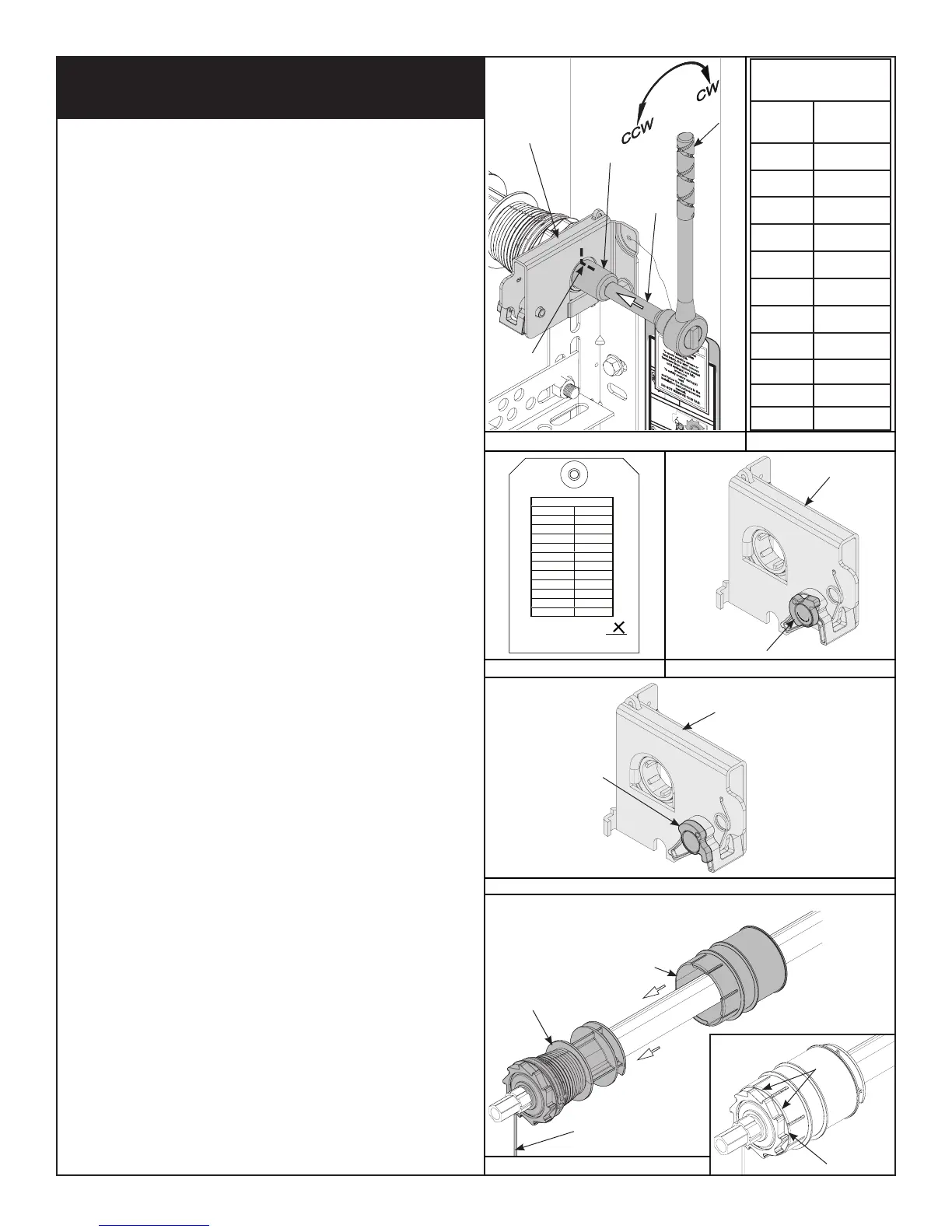
Anytime spring adjustments are made, ratchet pawl knob must be in the
upper position to add/remove required number of spring turns. To adjust
springs, only add or remove a maximum of 3/10 of a turn (three teeth of
ratchet wheel) at a time. Both sides need to be adjusted equally on double
spring doors.
IMPORTANT: BE PREPARED TO HOLD THE FULL TENSION OF THE SPRING,
WHEN ADJUSTING SPRING TENSION.
IMPORTANT: DO NOT ADD OR REMOVE MORE THAN 1 SPRING TURN
(1 SPRING TURN EQUALS 10 TEETH ON RATCHET WHEEL) FROM THE
RECOMMENDED NUMBER OF TURNS SHOWN ON THE SPRING TURN CHART.
Add Spring Tension: The ratchet wheel is made of 10 teeth. To add spring
tension, ensure the ratchet and socket is set so that it will tighten counter
clockwise on the right hand side, and clockwise on the left hand side. Place
the ratchet with 5/8” socket onto the winding shaft, pull down to add 3/10 of
a turn. Watch as three teeth of the ratchet wheel pass over the pawl, creating
three “clicks”.
Remove Spring Tension: To remove spring tension, ensure the ratchet and
socket is set so that it will tighten counter clockwise on the right hand side
and clockwise on the left hand side. It is recommended that a regular 5/8”
wrench be used. Place the wrench onto the winding shaft. Pull down on the
wrench to relieve pressure between the pawl and the ratchet wheel. Push
in on the pawl to allow the three ratchet wheel teeth to pass by the pawl, as
you carefully allow the wrench to be rotated upward by the spring tension.
Release the pawl to allow it to engage with the ratchet wheel.
If the door still does not operate easily, lower the door into the closed
position, UNWIND SPRING(S) COMPLETELY, and recheck the following items:
1.) Check the door for level.
2.) Check the TorqueMaster
®
tube and flagangles for level and plumb.
3.) Check the distance between the flagangles. It must be door width plus
3-3/8” to 3-1/2”.
4.) Check the counterbalance cables for equal tension. Adjust if necessary.
5.) Rewind the spring(s).
6.) Make sure door isn’t rubbing on jambs.
To install drum wraps, position the left hand drum wrap over the left hand
drum, align with counterbalance cable; slide groove in drum wrap towards
the left until tabs snap over drum in between drum and ratchet gear, as
shown in Fig. 4.1. Repeat for right hand side.
TorqueMaster
®
Plus Single and Double Spring Replacement
- Continued
End Bracket
Ratchet
3”
Extension
5/8” Socket
Marks
Pawl Knob In
Lower Position
End Bracket
Pawl Knob In
Upper Position
End Bracket
Drum Wrap
(Left Hand)
Drum
(Left Hand)
Counterbalance
Cable
Groove
In Drum
Tabs
RECOMMENDED
SPRING TURNS
Door
Height
Spring Turns
6’-0” 14
6’-3” 14-1/2
6’-5” 15
6’-6” 15
6’-8” 15-1/2
6’-9” 15-1/2
7’-0” 16
7’-3” 16-1/2
7’-6” 17
7’-9” 17-1/2
8’-0” 18
FIG. 3.6
FIG. 3.8
FIG. 3.9
FIG. 4.0
FIG. 4.1
FIG. 3.7
 Loading...