5
IMPORTANT! RIGHT AND LEFT HAND IS ALWAYS DETERMINED FROM INSIDE
THE BUILDING LOOKING OUT.
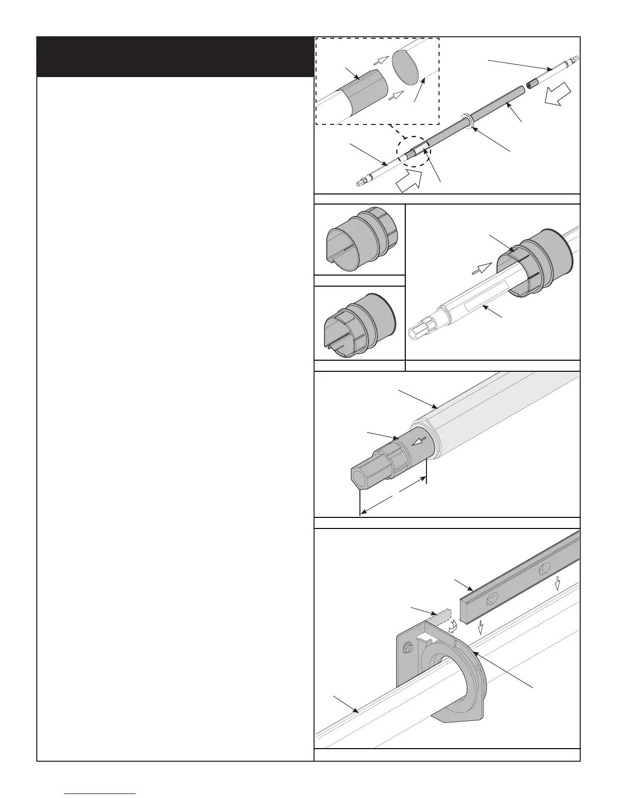
Slide the new spring(s), perch end first, into the torque tube (each spring is
identified as to right and left hand, on the perch), as shown in Fig. 2.3. For
single spring applications, there will be no left hand spring inserted into the
TorqueMaster
®
spring tube assembly.
STEP 1:
If you have a rear mount low headroom counterbalance system, which has
no drum wrap, skip this step and proceed with STEP 2.
NOTE: Drum wraps must be installed prior to installing the TorqueMaster
®
Plus end bracket. Drum wrap installation after the end bracket is installed, is
not possible without removing the end bracket and it’s components.
Drum wraps are identified as right and left. Slide the left hand drum wrap
over the left side of the TorqueMaster
®
spring tube assembly with the tabs
facing left. Continue sliding the left hand drum wrap towards the center of
the TorqueMaster
®
spring tube assembly.
STEP 2:
Slide the right hand drum wrap over the right side of the TorqueMaster
®
spring tube assembly with the tabs facing right. Continue sliding the right
hand drum wrap towards the center of the TorqueMaster
®
spring tube
assembly, as shown in Fig. 2.4.
Shake the TorqueMaster
®
spring tube assembly gently to extend the winding
shafts out about 5" on each side, as shown in Fig. 2.5. Lift the torque tube
assembly up and align the center bushing into the center bracket. Check
torque tube for level and adjust if necessary. Bend the center bracket tab
back over the center bushing, as shown in Fig. 2.6.
Cable drums and TorqueMaster
®
spring tube assembly are cam shaped to fit
together only one way. To install the cable drum, slide the correct cable drum
over the winding shaft until the cable drum seats against the TorqueMaster
®
spring tube assembly, as shown in Fig. 2.7.
Standard Lift/Front Mount Low Headroom Applications:
The winding shaft must extend past the cable drum far enough to expose the
splines and the groove. Align the winding shaft groove with the round notch
in the flagangle, as shown in Fig. 2.9.
Rear Mount Low Headroom Applications:
The winding shaft must extend past the cable drum far enough to expose the
splines and the groove. Align the winding shaft groove with the round notch in
the adapter bracket, as shown in Fig. 3.0.
For single spring applications: Insert the loose winding shaft into the left
hand cable drum prior to sliding the cable drum over the TorqueMaster
®
spring tube assembly, as shown in Fig. 2.9.
NOTE: On single spring applications, take care in handling the loose winding
shaft (left side) so that it does not slide back into the TorqueMaster
®
spring
tube assembly, as shown in Fig. 2.9.
Adjust the cable drum assembly by rotating the cable drum to the same
amount of cable drum wraps that was previously made.
NOTE: Cable drums require either 1/2 to 3/4 or 1 1/2 to 1 3/4 wraps.
If cable tension is slack, loosen the set screw no more than 1/2 turn and pull
on the end of the cable to remove all slack. Snug the set screw, then tighten
an additional 1-1/2 turns, as shown in Fig. 2.8.
IMPORTANT! ENSURE THE CABLE IS ALIGNED AND SEATED IN THE FIRST
GROOVE OF THE CABLE DRUM.
For double spring applications: Repeat for opposite side.
TorqueMaster
®
Plus Single and Double Spring Replacement
FIG. 2.3
FIG. 2.6
Perch
Left Hand
Spring
Right Hand
Spring
TorqueMaster
®
Tube
Bend The Center Bracket
Tab Over Center Bushing
Center Bracket Bushing
Center Bracket Bushing
Level
TorqueMaster
®
Tube
Winding
Shaft
5”
TorqueMaster
®
Spring Tube
Assembly
FIG. 2.4
TorqueMaster
®
Tube
Drum Wrap
Right Drum Wrap
Left Drum Wrap
FIG. 2.5
TorqueMaster
®
Tube
TorqueMaster Labeled End