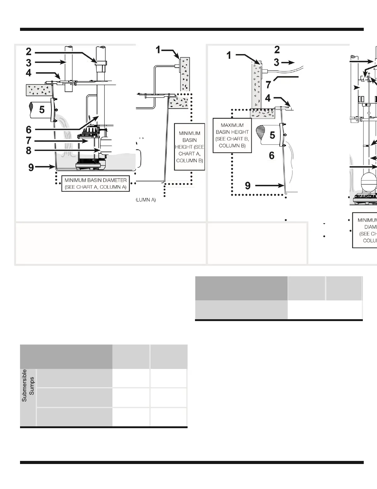
1. GFCI OUTLET 5. PIPE INLET
2. CHECK VALVE 6. DISCHARGE PIPE
3. VENT PIPE 7. SUMP PUMP
4. GASKET/BASIN LID 8. SWITCH (SEE CHART A, ON
PAGE 3)
TYPICAL SUMP INSTALLATION
1. This installation must be in accordance with the National
Electric Code and all applicable local codes and
ordinances.
2. Use a basin that is large enough to accommodate the
pump. The minimum requirements for the sump pumps
are:
3. Clean the basin of all debris.
4. Assemble switch or float if needed. Refer to warranty
and service parts sheet for specific directions.
5. Set the pump on a solid, level surface. Do not place
pump directly on clay, earth, gravel or sand. A brick or
block may be installed under the pump to provide a solid
base.
6. Position pump so the switch is away from the inlet so
switch is clear from incoming water. Verify the switch has
at least 1 in. clearance to the side wall of the basin and is
free to move throughout its movement. If optional control
device or float is used, follow mounting instruction
supplied with device or float.