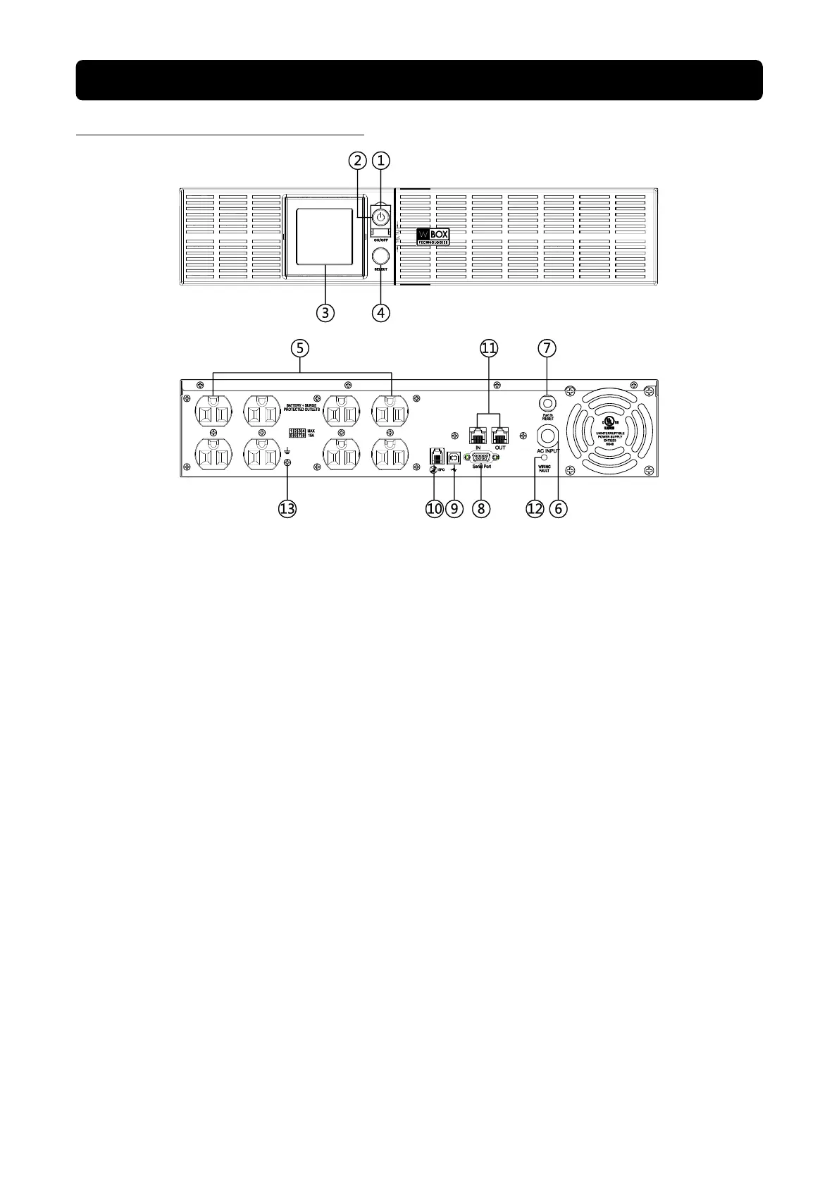
FRONT / REAR PANEL DESCRIPTION
1. Power Switch
Master on/off switch for equipment connected to the UPS.
2. Power On Indicator
An LED ring around the Power Switch indicates that the AC utility input power condition is normal and
that the UPS outlets are providing power, free of surges and spikes.
3. Multifunction LCD Readout
An LCD that shows various UPS information using icons and messages.
4. Display Toggle Button
Used to select among a variety of information the LCD can display.
5. Battery Backup, Surge Protected and AVR protected Outlets
This unit provides a total of 8 outlets with battery backup and surge protection. They ensure that
connected equipment will keep an uninterrupted operation over a period of time, during a power
failure.
6. AC Input Power Cord
Connect the AC Power cord to a properly wired and grounded outlet.
7. Input Circuit Breaker
The circuit breaker serves to provide input overload and fault protection.
8. Serial Port
The serial port allows communication between the UPS and the computer. The UPS can control the
computer’s shutdown in case of an emergency, and the computer can monitor the UPS and alter its
various programmable parameters.
 Loading...