4 | Installation
6 / 12 5911743-A-01 Webasto Go
ger module detects an output ground fault, it will shut
down power to the output cable and illuminate the RED in-
dicator.
l Insulation: The charger module, adapter, cable assembly,
and charge coupler are completely insulated (no exposed
live parts) to protect against electric shock.
l Unintentional Disconnection: The charge coupler is de-
signed to minimize unintentional disconnection. A pilot sig-
nal wire in the cable and charge coupler eliminates the pos-
sibility of electric shock when not connected to a vehicle or
if an unintended disconnect occurs during a charge. Dis-
connection during charging is safe.
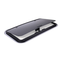
4 Installation
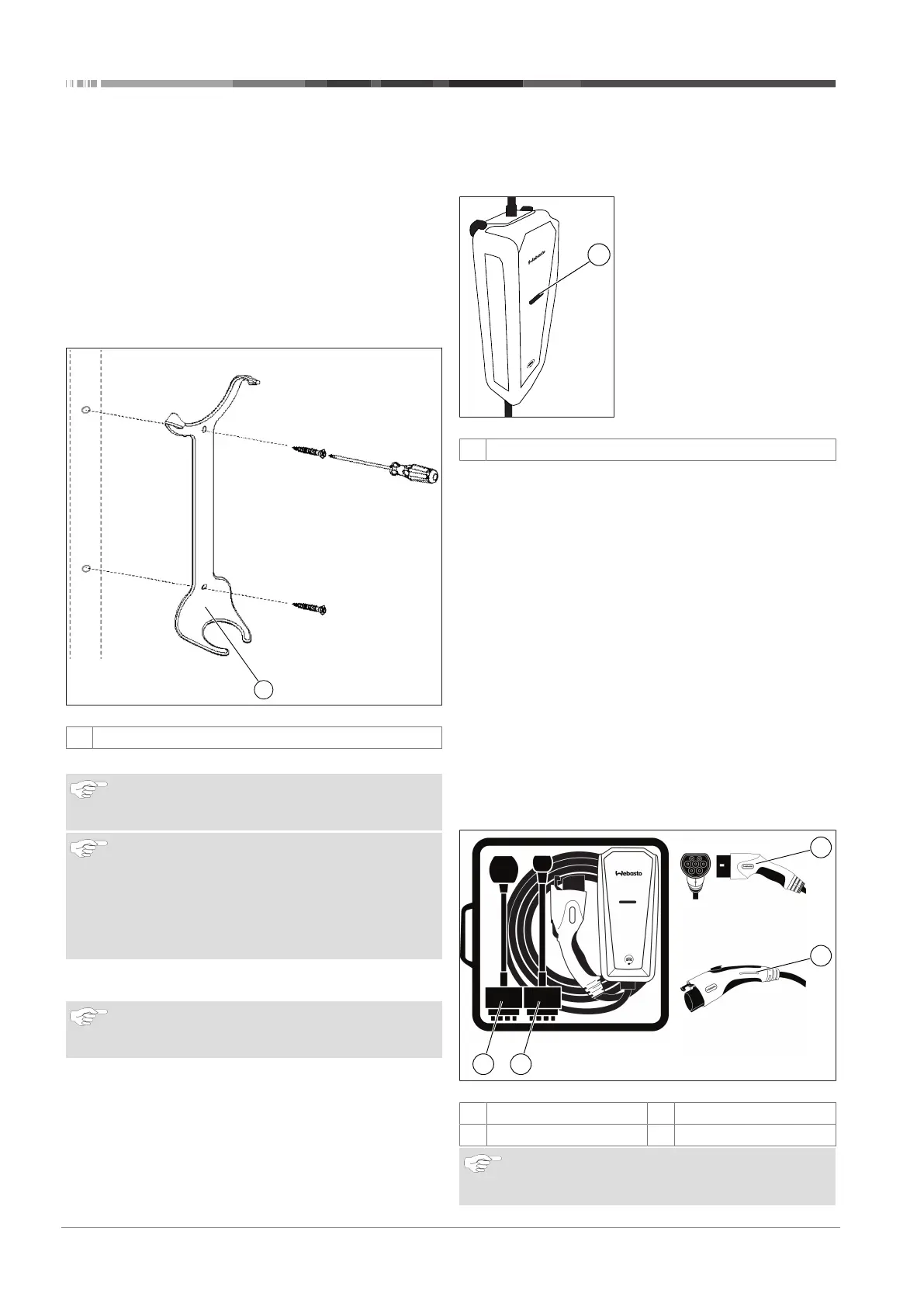
Fig.6 Wall hanger
1
Wall hanger
1. Choose a location to install the wall hanger.
NOTE
The Webasto Go Mobile Charger can be used indoors
and outdoors.
NOTE
The hanger should be located in practical proximity to
both the utility receptacle or plug, and the location of
your vehicle’s charge receptacle, preferably mounted to
a wall stud.
Drywall and masonry wall installations require the use
of appropriate fasteners.
2. Measure up approximately 8 inches / 20 cm from the de-
sired receptacle and mark the location.
NOTE
Before drilling any holes, verify that the control box will
sit in hanger after it is plugged in.
3. Drill out the preferred mounting holes through the back of
the wall hanger using a 7/32 inch / 5.6 mm drill bit.
4. Using a screwdriver, tighten the screws for the wall hanger.
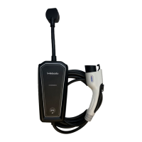
5 Using your Webasto Go
Mobile Charger
5.1 Indicator light
Fig.7 Webasto Go Mobile Charger
1
Indicator light
The indicator light on your charger is the first thing you will no-
tice when you are about to plug or unplug your vehicle. Before
getting started, here is a simple explanation of the indicators.
AMBER Indicator
The AMBER Indicator illuminates to indicate the charger is re-
booting after an error. Refer to the chapter8.1, "Troubleshoot-
ing" on page 9 for more information.
BLUE Indicator
When plugged into the wall socket, the BLUE Indicator illumin-
ates to indicate the charger is ready to use. During charging, the
BLUE Indicator will pulse on and off every two seconds. Refer to
the chapter8.1, "Troubleshooting" on page 9 for more in-
formation.
RED Indicator
The RED Indicator illuminates when the charger detects an er-
ror. If the RED Indicator illuminates, the charger will not deliver
power to the vehicle. The error must be corrected before a
charging cycle can begin or continue. Refer to the chapter8.1,
"Troubleshooting" on page 9 for more information.
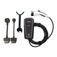
5.2 Charging Your Vehicle
Fig.8 Webasto Go Mobile Charger
1
Type 1 IEC Coupler
2
Type 2 SAE Coupler
3
Low Power Adapter
4
High Power Adapter
NOTE
If Wall bracket is not used for mounting the cordset,
plug cordset to wall socket closer to ground.