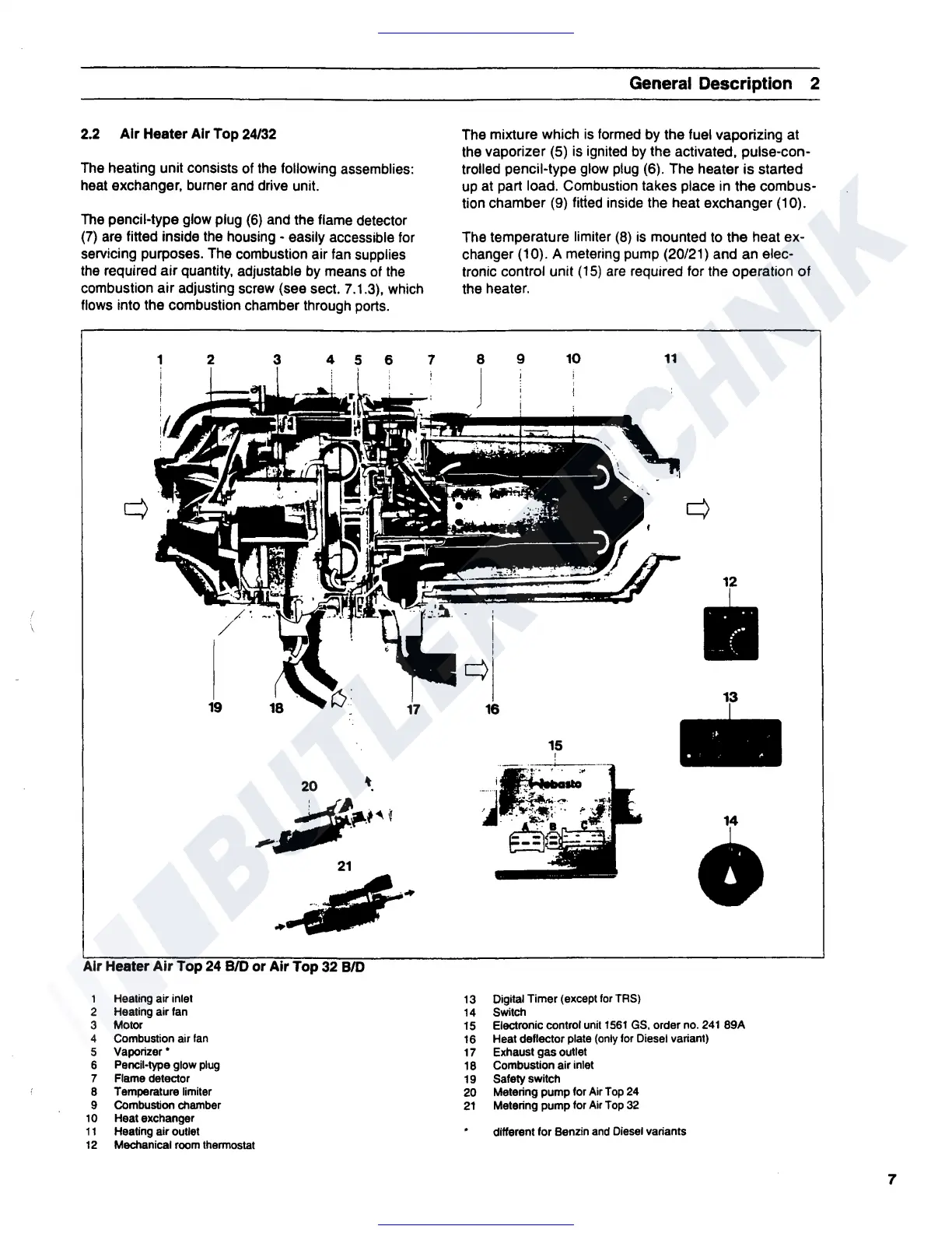
2.2 Air Heater Air Top 24/32
The heating unit consists of the following assemblies:
heat
exchanger,
burner and drive unit.
The pencil-type glow plug
(6)
and the flame detector
(7)
are fitted inside the housing - easily accessible for
servicing purposes. The combustion air fan supplies
the required
air
quantity, adjustable by means of
the
combustion
air
adjusting screw
(see
sect. 7 .1.3), which
flows into the combustion chamber through ports.
1
2
19
3 4 5 6
'
21
--~·
.
..,,.
Air Heater Air Top 24
B/0
or
Air Top 32
BID
1
2
3
Heating air inlet
Heating air
Ian
Motor
4 Combustion air
Ian
5 Vaporizer•
6
Pencil-type
glow
plug
7
Flame
detector
B
Temperature
limiter
9
CombuStion
chamber
10
Heatexchanger
11
Healing
air
outlet
12
Mechanical
room
lhennostat
7
General
Description 2
The mixture which is formed by the fuel vaporizing at
the vaporizer (5) is ignited by the activated, pulse-con-
trolled pencil-type glow plug (6). The
heater
is
started
up at part load. Combustion takes place in
the
combus-
tion chamber (9)
fitted inside the heat exchanger (10).
The temperature limiter
(8)
is mounted to the heat ex-
changer (10). A metering pump (20/21) and an elec-
tronic control unit
(15)
are
required for the operation
of
the heater.
9
10
11
q
Yr
,.
.
■
13
15
i
:··j
,_:.
~-.
~
...
- -
--
•
13
Digital Timer (exceptlor
TRS)
14
Switch
15
Electronic control
unit
1561
GS,
order
no.
241
89A
16
Heat deflector
plate
(only
for
Diesel
variant)
17
Exhaust gas outlet
18 Combustion air inlet
19
Safety switch
20
Metering pump for Air
Top
24
21
Metering pump for
Air
Top
32
different for Benzin
and
Diesel
variants
7
 Loading...