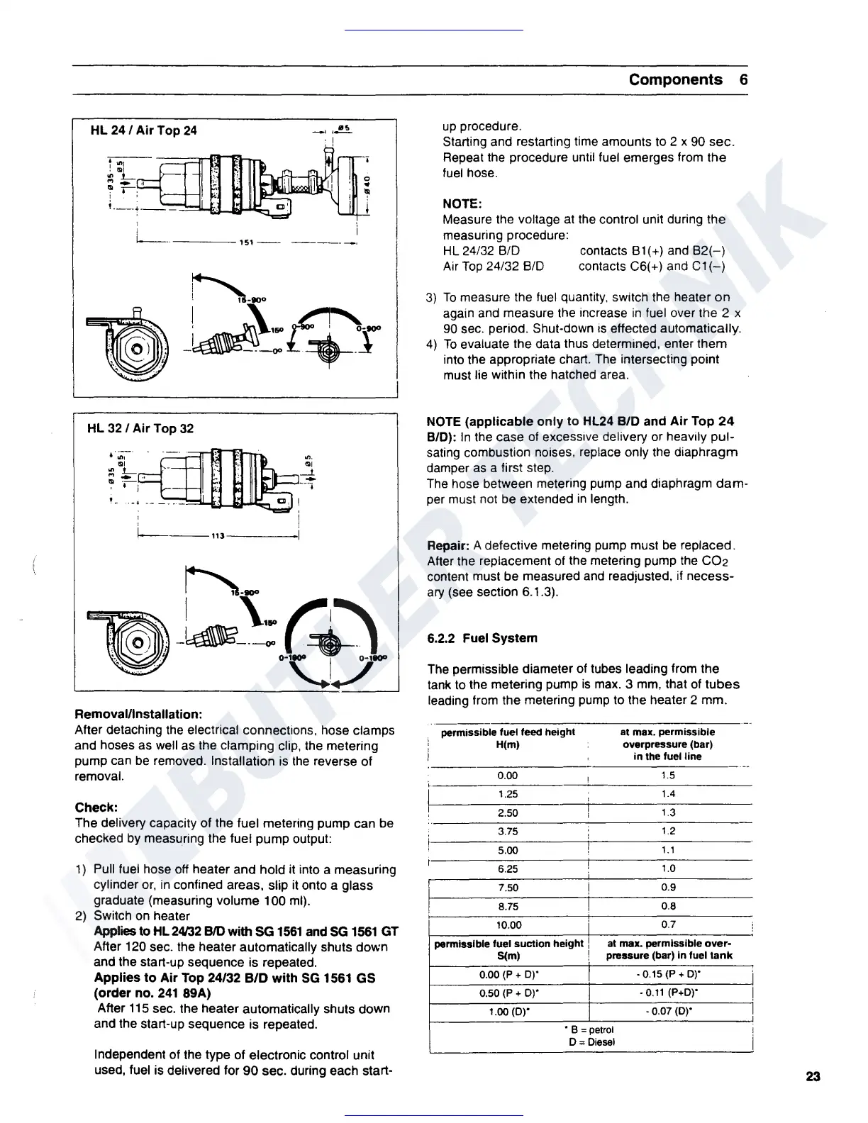
HL 24 / Air Top
24
! ..
.,
•
"'L
M
...
!I
~
.------.
' '
I
I
1----
----151
--
-----
-·
HL
32
/ Air Top
32
,;;-·
..
,
.,
1__
f"'I
....
,
.,
__
I • )
1
1------113-----
Removal/Installation:
After detaching the electrical connections, hose clamps
and hoses as well as the clamping clip, the metering
pump can
be
removed. Installation is
the
reverse of
removal.
Check:
The delivery capacity of the fuel metering pump can be
checked by measuring the fuel pump output:
1)
Pull fuel hose off heater and hold it into a measuring
cylinder
or,
in
confined areas, slip it onto a glass
graduate {measuring volume 100 ml).
2)
Switch
on
heater
Applies
to
HL24/32
BID
with
SG
1561
and
SG
1561
GT
After 120 sec. the heater automatically shuts down
and the start-up sequence is repeated.
Applies
to
Air
Top
24/32 B/D with
SG
1561 GS
(order no.
241
89A)
After
115
sec. the heater automatically shuts down
and the start-up sequence is repeated.
Independent of the type of electronic control unit
used, fuel is delivered for
90
sec. during each start-
Components 6
up
procedure.
Starting and restarting time amounts to 2 x 90 sec.
Repeat the procedure until fuel emerges from the
fuel
hose .
NOTE:
Measure the voltage at the control unit during the
measuring procedure:
HL
24/32 8/D
Air
Top
24/32 8/D
contacts
81(+) and
82(-)
contacts C6(+) and
C1(-)
3)
To
measure the fuel quantity, switch the heater
on
again and measure the increase
in
fuel over the 2 x
90
sec. period. Shut-down is effected automatically.
4)
To
evaluate the data thus determined, enter them
into the appropriate chart. The intersecting point
must lie within the hatched area.
NOTE
(applicable only to HL24 B/D and Air Top
24
B/D):
In
the case
of
excessive delivery or heavily pul-
sating combustion noises, replace only the diaphragm
damper
as
a first step .
The hose between metering pump and diaphragm
dam-
per must not be extended
in
length.
Repair:
A defective metering pump must
be
replaced.
After the replacement of the metering pump the CO2
content must be measured and readjusted, if necess-
ary
(see section 6.1.3).
6.2.2 Fuel System
The permissible diameter of tubes leading from the
tank to the metering pump
is
max.
3
mm,
that of
tubes
leading from the metering pump to the heater 2 mm.
permissible fuel feed height
H(m)
0.00
1.25
2.50
3.75
5.00
6.25
7.50
8.75
10.00
I
!
I
permissible fuel suction height I
S(m) !
0.00
(P
+ D)'
0.50
(P
+
D)'
1.00
(D)'
at max. permissible
overpressure (bar)
in the fuel line
1.5
1.4
1.3
1.2
1.1
1.0
0.9
0.8
0.7
at
max. permissible
over-
pressure (bar) In fuel
tank
• 0.15
(P
+ D)'
•
0.11
(P+D)'
·0.07
(D)'
• B =petrol
D = Diesel
!
i
I
!
I
I
23
 Loading...