30
6 Components
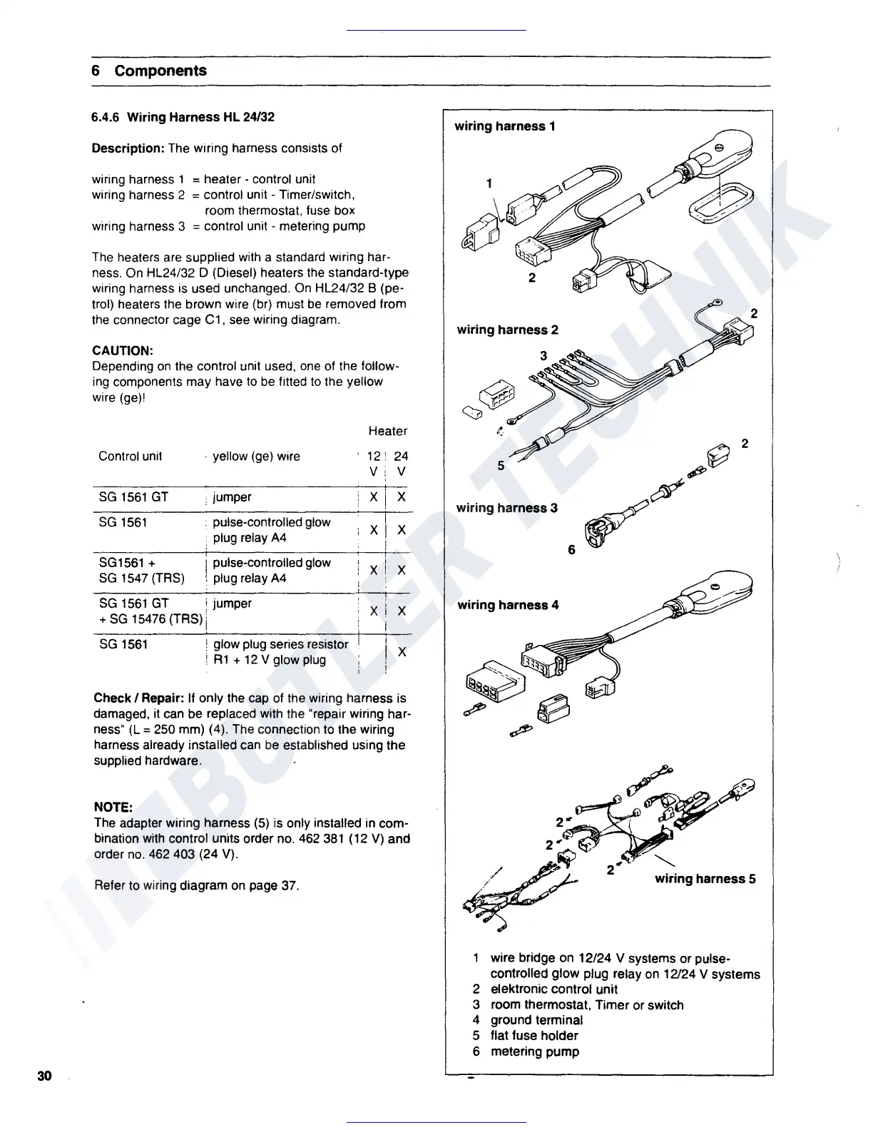
6.4.6 Wiring Harness HL 24/32
Description:
The wiring harness consists of
wiring harness 1
= heater - control unit
wiring harness 2
= control unit - Timer/switch,
room thermostat, fuse box
wiring harness 3
= control unit - metering pump
The heaters
are
supplied with a standard wiring har-
ness. On HL24/32 D (Diesel) heaters the standard-type
wiring harness is used unchanged.
On
HL24/32 B (pe-
trol) heaters the brown wire (br) must
be
removed from
the
connector cage C1, see wiring diagram.
CAUTION:
Depending
on
the control unit used,
one
of the follow-
ing
components may have
to
be
fitted
to
the yellow
wire (ge)I
Heater
Control unit
• yellow (ge) wire
12'
24
V:
V
SG
1561
GT
; jumper
xj
X
SG
1561
• pulse-controlled glow
i
• plug relay
A4
XI
X
SG1561
+ I pulse-controlled glow
X X
SG
1547
(TRS)
',
plug relay
A4
SG
1561
GT
i jumper
X X
+
SG
15476 {TRS) j
SG
1561
! glow plug series resistor
X
;
A1
+
12
V glow
plug
Check/
Repair:
If
only the cap of the wiring harness is
damaged, it can be replaced with the "repair wiring har-
ness"
(L
= 250 mm) (4). The connection
to
the wiring
harness already installed can
be
established using the
supplied hardware.
NOTE:
The adapter wiring harness
(5)
is only installed
in
com-
bination with control units order no. 462
381
{
12
V)
and
order
no.
462 403 {24
V).
Refer to wiring diagram
on
page 37.
wiring
harness
1
wiring
harness
2
2
5
~~
wiring harness 3
~~
6
wiring harness 4
~sa;"-
-
~
.
~
wire bridge
on
12/24 V systems or pulse-
controlled glow plug relay
on
12/24 V systems
2 elektronic control unit
3 room thermostat, Timer or switch
4 ground terminal
5 flat fuse holder
6 metering pump
 Loading...