38
9 Wiring diagrams
F2
SA
@,...~
ft"
L,_J
• •
+--opt
i..~:n
KS;
I
X4
---+-"'-
.......
~----,
S6
w,*
Lal~•
C-CIONNCtiartl
5-:1..._
dN
conai.ctan
S,u,cn
0.
cavi
-
..
,,
...
.......
B
C
K1
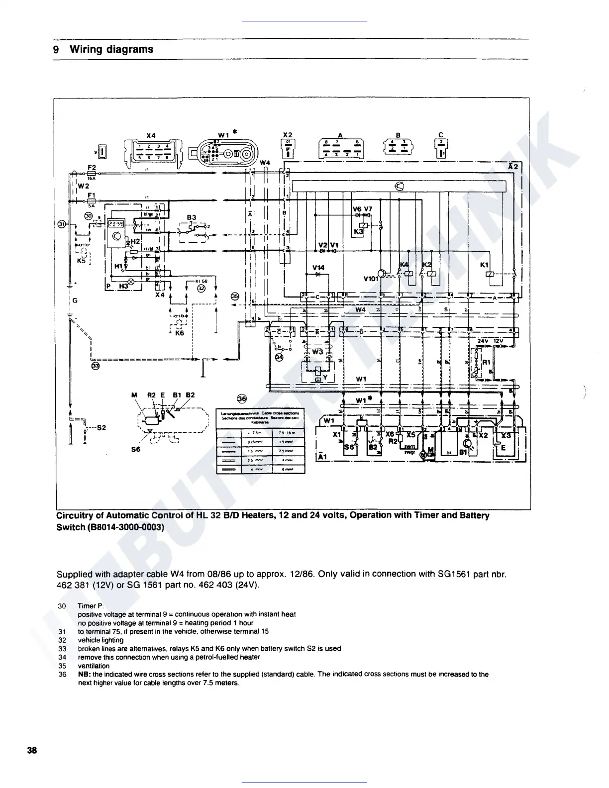
Circuitry
of Automatic Control
of
HL 32 BID Heaters, 12 and
24
volts,
Operation with Timer and Battery
Switch (B8014-3000-0003)
Supplied
with
adapter cable W4 from 08/86 up to approx. 12/86. Only valid in connection with
SG1561
part
nbr.
462
381
(12V)
or
SG
1561
part no. 462 403 (24V).
30 TimerP:
positive voltage at terminal 9
= continuous operation with instant heat
no positive voltage
at
terminal 9 = heating period 1 hour
31
to terminal
75.
if present
in
the vehicle. otherwise terminal
15
32
vehicle lighting
33
broken lines are alternatives, relays
KS
and K6 only when battery switch
S2
is used
34
remove
this
connection when using a petrol-fuelled heater
35
ventilation
36
NB: the indicated wire cross sections refer to the supplied (standard) cable.
The
indicated cross sections must be increased to the
next higher value for cable lengths over 7.5 meters.
 Loading...