Wiring
diagrams 9
E
[ITT
F2
F1
-S4
HL24
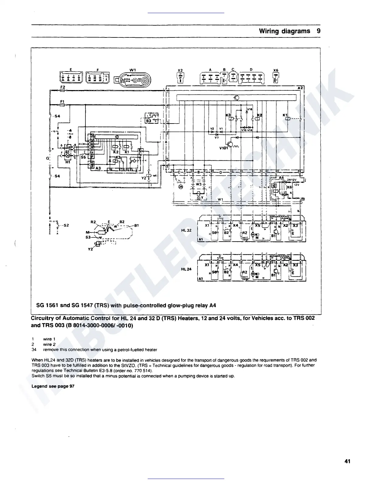
SG
1561 snd
SG
1547 (TRS) with pulse-controlled glow-plug relay
A4
Circuitry
of
Automatic Control for
HL
24 and 32 D (TRS) Heaters, 12 and 24 volts, for Vehicles acc. to TRS 002
and
TRS
003 (B 8014-3000-0006/ -0010)
1 wire 1
2 wire 2
34
remove this connection when using a petrol-fuelled heater
When HL24 and
320
(TRS) heaters are to be installed
in
vehicles designed for the transport of dangerous goods
the
requirements
of
TRS 002 and
TRS 003 have to
be
fulfilled
in
addition to the StVZO. (TRS = Technical guidelines for dangerous
goods•
regulation
for
road
transport). For further
regulations see Technical Bulletin E3-5.8 (order no. 770 514).
Switch
55
must be
so
installed that a minus potential is connected when a pumping device
is
started up.
Legend see page 97
41
 Loading...