Roof-Mounted Air Conditioner KK2000 E
Page 17 / 30
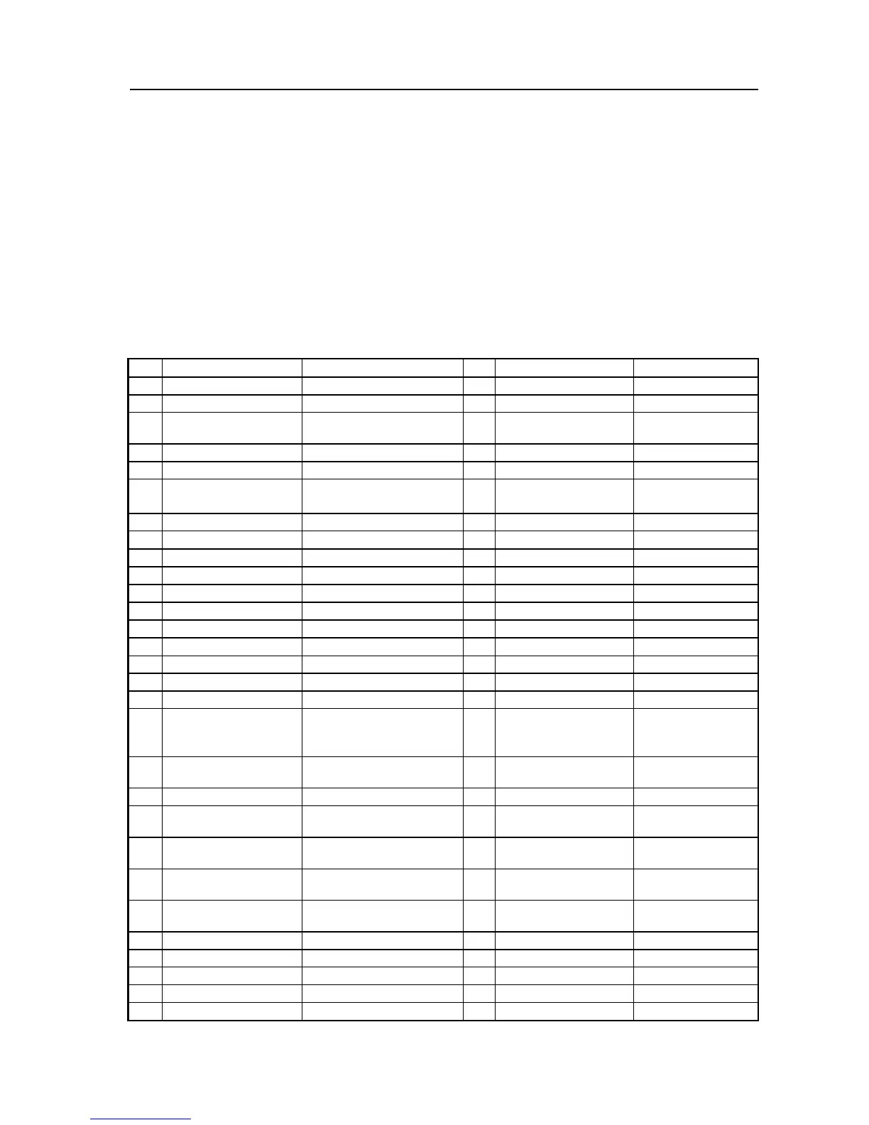
Key to circuit diagram:
1 Switch mounted in the vehicle console. 1x set value indicator, 2x switch
2 Hydro line
3 Take appropriate steps to ensure that there cannot be feedback to the board power
and the air conditioner.
4 Possible safety switch
5 Terminal 61 or terminal 15
6 The additional blower must be triggered by the heater unit at least at level 2.
7 K line diagnosis
8 CO
2
adjustment
9 COMPRESSOR
Item Description Item Description Comment
A1 Heater unit M1 Engine Condenser blower
A2 Controller M2 Engine Vaporizer blower
M3 Engine Fuel and hot air
blowers
B1 Thermostat module M4 Engine Additional blowers
B2 Temperature gauge
B3 Temperature gauge Overheat protection P Combi time switch Time Switch and
set value indicator
B4 Temperature gauge
S1 Pressure switch Blower 1/2/3
E Light pin/flame detector
S2
Thermostat switch Icing protection
S3 High pressure switch
F1 Fuse 15A
Blade-type fuse as SAE J 1284
S4 Low pressure switch
F2 Fuse 15A
Blade-type fuse as SAE J 1284
S5 Pressure switch Cooling ON/OFF
F3 Fuse 7.5A
Blade-type fuse as SAE J 1284
S6 Switch Additional blowers
F4 Fuse 15A
Blade-type fuse as SAE J 1284
F5 Fuse 8A S7 set value indicator Cool
F6 Fuse 25A X1 2 pin plug-in connection at A2 (STB)
X2 2 pin plug-in connection at A2 (STV)
H1 LED red (at pos. P) Light up immediate heater
button, ready indicator
Power on control
X3 2 pin plug-in connection at A2 (STU)
H2 Heating symbol in the
display (at P)
Operating indicator X4 2 pin plug-in connection at A2 (STZ)
H3 Lights (at P) Key and display lighting X5 2 pin plug-in connection at A2 (STY)
H4 Lights (at S1) Power on control for the
cooling
X7 12 pin plug-in
connection
at A2 (ST1)
H5 Lights (at S5) Power on control for the
cooling
X11 2 pin plug-in connection at Y
X12 12 pin plug-in
connection
at P
K1 Relay X13 15 pin plug-in
connection
K2 Relay X14 15 pin terminal strip
K3 Time relay X15 2 pin plug-in connection
K4 Relay X16 4 pin plug-in connection at S7
K5 Relay
K6 Relay Y Metering pump