Roof-Mounted Air Conditioner KK2000 E
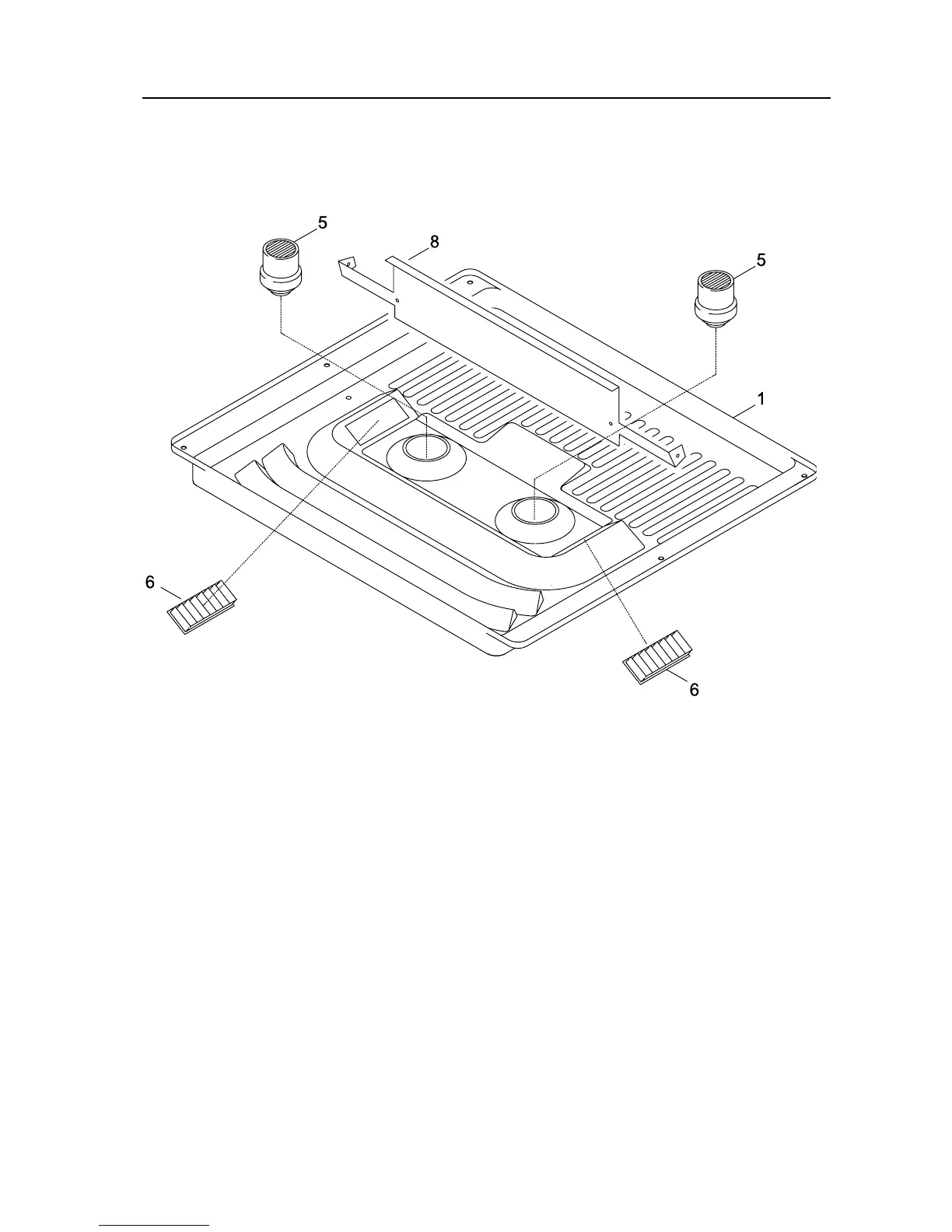
2.2 Air Manifold Plate
The air manifold plate (figure 2.3) contains:
– Air manifold plate (1) with dividing sheet (8)
– Adjustable air blowers (5,6)
F
Figure 2.3.
2.3 Electrics
The circuit diagrams for the KK2000 E are shown in figure 3.1.
The connection must use a battery discharge protection switch with a fuse. This way the
system can only be operated when the vehicle engine is running.
2.4 Workings of the Air Conditioning
2.4.1 Ventilation
Turn the thermostat to the far left (OFF).
Turn the blower switch from OFF to the right to level 1, 2, or 3, depending on the
amount of air desired. By adjusting the dischargers (5,6 figure 2.3), you can change the
air flow to suit your individual needs. The flow from the slots remains constant for the
front windshield.
Page 8 / 30