Section B - ComponentsJBE(X) Manual
Page 15
Multiple Setting Modulating Motor
In some burner congurations, there are different ideal
settings for oil and gas ring, especially when higher
turndown is desired. This can be accommodated with an
optional modulating motor that has different low re and
high re positions for gas vs oil.
This optional modulating motor uses 4 to 8 internal
switches. One switch is used to prove the high re purge
position during pre-purge. A second is used to prove the
fully closed position. This is the position of the motor
when the burner is off. A third switch is used to prove the
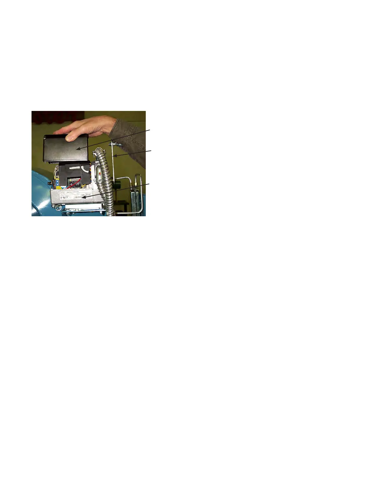
Removable
Cover
Drive
Arm
Modulating
Motor
Figure B-18 Siemens Mod Motor Adjustments
ignition position – the point at which the burner will light.
A fourth switch is the low re position. This is the position
of lowest ring. It can be different from the ignition
position. If the burner is a combination gas-oil burner,
two additional switches may be used. These do the
same function as the third and fourth switches already
listed, but can be set up to allow for different ignition and
low re positions for gas and oil operation. There is also
a 7th and 8th switch that can be used to accommodate
two different high re settings. See the burner wiring
diagram to determine switch numbers and functions.
Oil Limiting Potentiometer
The fan is sized for air at rated capacity plus the quantity
of FGR required for gas NOx emissions. When ring oil,
the FGR rate is usually reduced, providing a larger fan
capacity than desired. To prevent the burner from over
ring on oil, a limiting potentiometer is used to limit the
oil rate. In this mode, the modulating motor is restricted
in its travel to something under 90
o
.
This potentiometer is located in the control panel and is
adjusted at startup to provide the correct oil ring rate.
Parallel Positioning System (Linkageless)
The Posi-Control system is a parallel positioning system
(linkageless) that uses individual actuators for each
control valve and a computer controller that directs each
actuator to provide the input change from minimum to
maximum capacity. The control provides more exibility
in setting each fuel rate (Figure B-2).
8. Electrical Controls
Control Panel
The control panel (Figure B-6) contains the ame
safeguard control, relays, terminal strips for electrical
connections and other components required for unit
control. Other components may be included for operation
of the boiler – a low water cutout relay, for example.
Flame Safeguard
The ame safeguard (Figure B-6) provides operational
control and safety sequencing for the burner. Safety
limits are tied to the unit and it controls the operation of
the fuel valves. The ame scanner is part of this and can
detect a ame failure, causing a shutdown. There are
several different ame safeguards available with different
features and costs. They can provide fault annunciation
and communications with other controls. The details of the
control used in the burner are supplied with the unit.
On-Off Switch
This switch is used to start and stop the burner by opening
or closing the limit circuit to the ame safeguard control.
Manual-Auto Switch and Potentiometer
The Man-Auto switch is used to select which signal source
is used for modulation control of the burner. With the switch
in the “Man” position, the burner ring rate is determined by
the position of the manual potentiometer. With the switch
in the “Auto” position, the burner ring rate is determined
by the signal from the boiler modulating controller. When
in the “Auto” position, the manual potentiometer can limit
the ring rate of the burner from anywhere between low re
and high re. The modulating motor will always drive open
and closed during pre-purge, regardless of the position of
the Man-Auto switch and potentiometer.
Fuel Transfer Switch
This switch selects the proper fuel for ring. It has a center
“off” position that prevents it from moving from one position
to the other, without stopping in the “off” position rst.
Power On light
Indicates that power is applied to the control panel.
Call For Heat light
Indicates the burner On-Off switch is closed and the boiler
limits are closed.
Fuel On light
Indicates the main fuel valve circuit has been energized.
Alarm light
Indicates the ame safeguard control is in a safety
shutdown and lockout condition. The ame safeguard
control reset button must be pressed before the burner can
operate again. On some burners, the Alarm light may also
be used to indicate other failure conditions such as low
water or high limit. See the wiring diagram for details on
what other controls may be wired to the Alarm light.