On combination fuel, linkage burners with FGR, the shutoff
FGR valve may require adjustment for oil ring. If the gas
NOx level is 60 ppm, no adjustment is needed and both
fuels can operate with he same FGR setting.
5. Fuel Cam Adjustments
The fuel cam needs to be checked for correct travel
and alignment. Positions can change during shipment
and installation and they must be reviewed prior to
startup. The fuel cams are mounted to the ends of the
jackshaft assembly. A cam follower link follows the prole
established by the
adjusting screws and drives the fuel
valve. A thin metal band is used between the screw and
cam follower to provide a smooth prole. The adjusting
screws are backed by compressed nylon inserts, which
provide a resistance to turning.
The cam (Figure E-4) should be checked for the following
conditions:
a. At the low re position, the roller should be between the
rst two adjusting screws. If not, adjust the position of the
cam accordingly, making sure to maintain the same low re
fuel valve position.
b. When the linkage is modulated from low to high re, the
roller must stay in the center of the adjusting screws within
1/8”. If needed, the two cam set screws can be loosened
and the cam moved to center it on the roller.
c. At high re, the roller should be between the last two
adjusting screws.
d. The adjusting screws should form a smooth contour
with no jumps between the screws.
e. In preparation of startup, the retention plate can
be removed temporarily to make it easier to adjust the
screws.
THE RETENTION PLATE MUST BE REPLACED
WHEN SETUP IS COMPLETE.
If the unit is equipped with a parallel positioning system
(linkageless), the control valves can be positioned
and operated in a similar manner, but accomplished
through the controller. Refer to the instruction manual
for details.
CAUTION
LINKAGE AND ACTUATOR MOUNTINGS CAN BE
BENT OR MOVED DURING SHIPMENT AND IN-
STALLATION. THEY MUST BE CHECKED PRIOR
TO OPERATION AND ANY FAULTS CORRECTED.
FAILURE TO CORRECT A MISALIGNED CONTROL
WILL RESULT IN PREMATURE FAILURE.
6. Air Damper Adjustments
Low re is set at the factory to an approximate position
(usually about 5
o
to 10
o
from vertical position).
Page 37
JBE(X) Manual Section E - Preliminary Adjustments
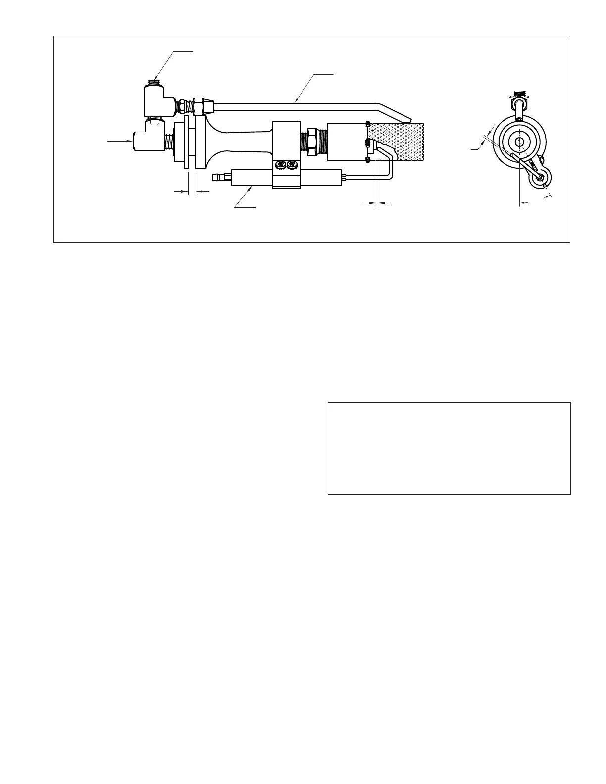
Figure E-5 Gas Pilot
30°
GAS SUPPLY
VENTURI AIR ADJUSTMENT
ELECTRODE & INSULATOR ASSY
1/16”
RAW GAS TUBE
RAW GAS ORIFICE ACCESS PLUG
1/16”