Section C - Installation
JBE(X) Manual
Page 20
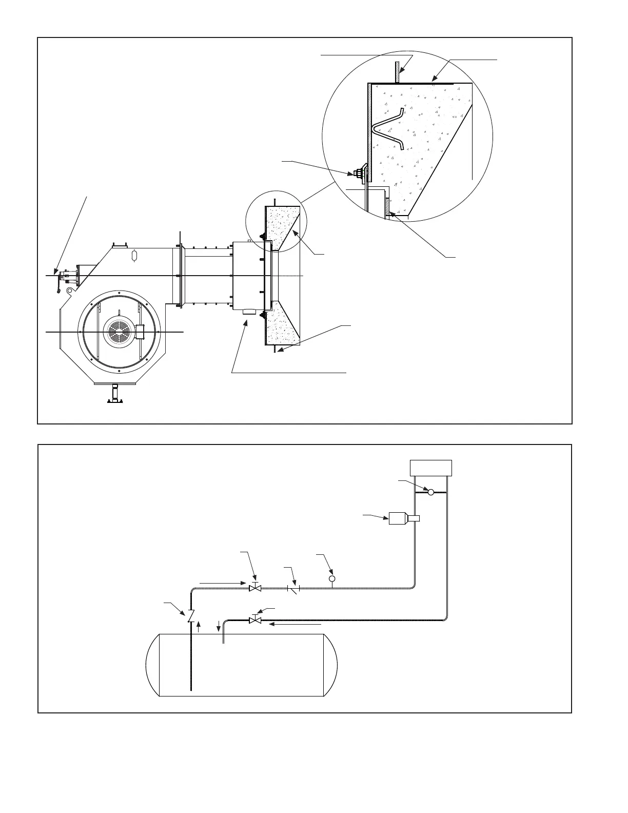
The burner must be level.
Tighten clamp bolts
uniformly - check after
ring for several hours.
This surface must be
sealed against the vessel.
Check vessel mounting
requirements.
Refractory
Front Plate
Figure C-3
Burner Mounting Instruction
Check Valve
(See Note)
Strainer
Shutoff Valve
Return to Tank
Supply to Pump
Shutoff Valve
Vacuum
Gauge
Oil Pump
Burner
Oil Pressure
Regulator
Fuel Oil Tank
Note: Location of check valve
varies with system. Check valve
is usually located as close as
possible to tank outlet.
Figure C-4
Typical #2 Oil Field Piping
The gas piping from the burner to the train
should have as few elbows as possible to
reduce pressure drop.
Attachment to vessel varies with manufacturer
(follow vessel manufacturers recommendation.
Fiberglass rope gasket
must be coiled to
cover the full mounting
ange surface.
Fill voids
between front
plate and
vessel with
ceramic blanket
4” deep or as
dened by
vessel
manufacturer.
Entire O.D. of
refractory should
be covered.