Page 31 Section D - Fuel and Electrical SystemsJBE(X) Manual
Suction Supply
Line
Return to Tank
(No Manual
Valves in This
Line)
Shutoff Valve
Strainer
Optional Low Oil
Pressure Switch
Typical Field Supplied Items - By Others
Pressure
Gauge
Solenoid
Valve
Solenoid
Valve
Oil Nozzle
(Bypassing)
Oil Pump
Check
Valve
Modulating
Oil Metering
Valve
Pressure
Gauge
Note: Oil Pump shipped loose
for eld piping & mounting
Typical Field Supplied Items - By Others
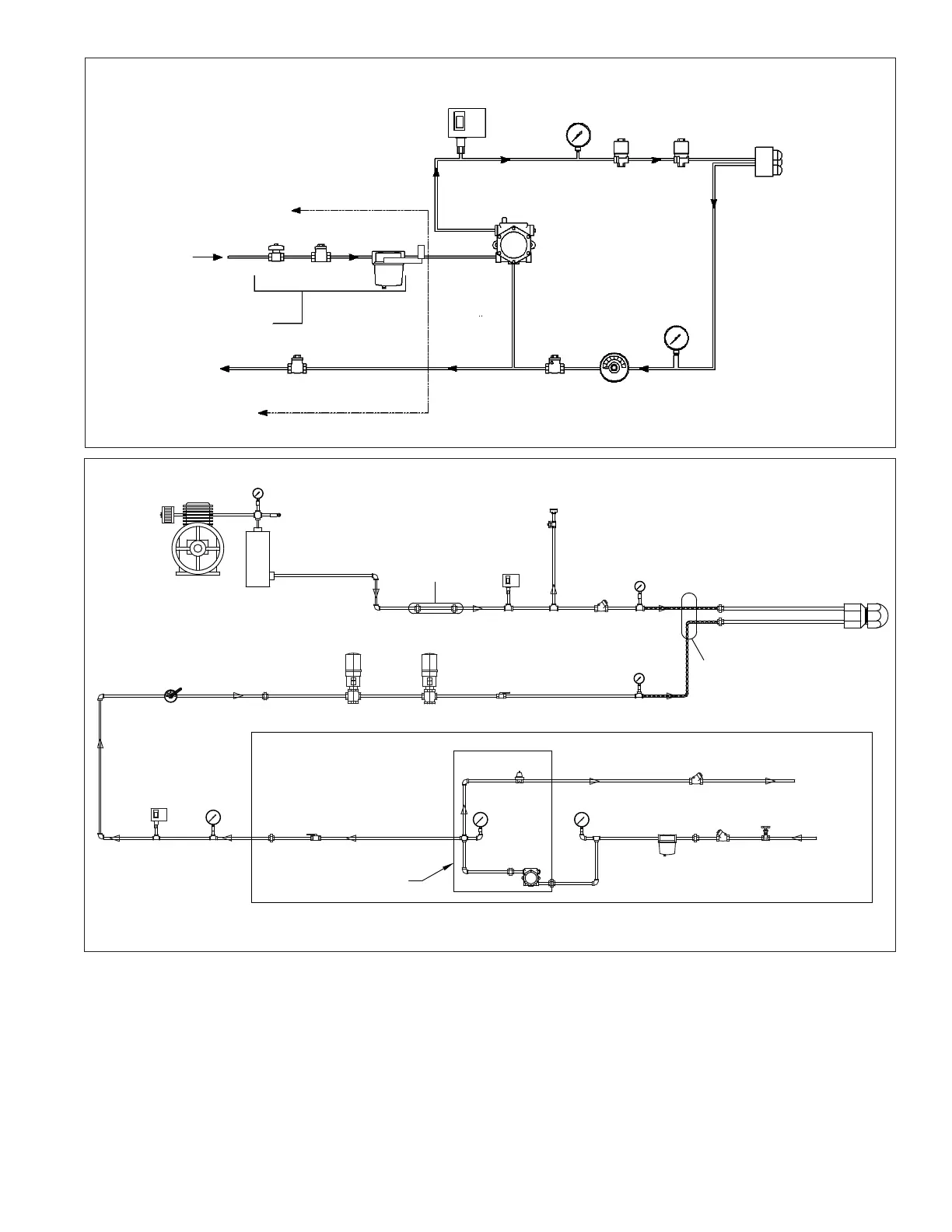
Figure D-3 Pressure Atomized Oil Schematic
Check
Valve
Relief Valve
Air Filter
Compressor
Safety
Oil Valve
Air Chamber
(200-300 BHP only)
Low Atomizing
Pressure
Switch
Silencer
Ball Valve to
Adjust Air Volume
(Modulating or
Fixed Position)
Check
Valve
Gauge
Flexible
Metal
Hoses Or
Copper
Tubing
Nozzle
Oil
Gauge
Ball
Valve
N.C. Main Oil
Valve
Oil
Metering
Valve
Low Oil
Pressure
Switch
Gauge
Ball or
Gate Valve
Gauge
Back Pressure Reg.
Compound Gauge
Oil Pump
Optional Pump Set
Factory Assembled
Strainer
Check Valve
Check
Valve
Gate
Valve
Return
to Tank
Oil
Suction
Typical Field Supplied Items By Others
Figure D-4
Air Atomizing Light Oil Schematic
A standard oil pump provides oil at a pressure of about
300 psi to the nozzle. At high re, the bypass is closed or
nearly closed and all of the pressure is available to the oil
nozzle for maximum ow. As the burner modulates to low
re, the oil metering valve is opened, causing some oil to
ow through the metering valve and to the return line. As
the metering valve continues to open, more oil is bypassed
and the ow through the nozzle continues to drop. At high
re, the pressure in the return line is about 150 psi. At low
re, this pressure drops to about 65 psi. Reducing the
pressure too low can result in poor atomization and a
smoky re, which limits the turndown to about 3:1. On
standard linkage systems, with combination gas, the
gas turndown will be about the same as the oil turn-
down, based on the air damper positions. Optional
multi-point modulation motors or parallel positioning
systems can be used to improve the turndown of gas
ring on a combination burner. The multi-point modu-
lation motor can provide different low re positions for
gas and oil, and therefore different turndowns.
Relief Valve Size At
Discharge
Opening In
Air Chamber
(Field Piped)