Infrared Remote Control and I/O
Expansion Module
English
CFW100 | 7
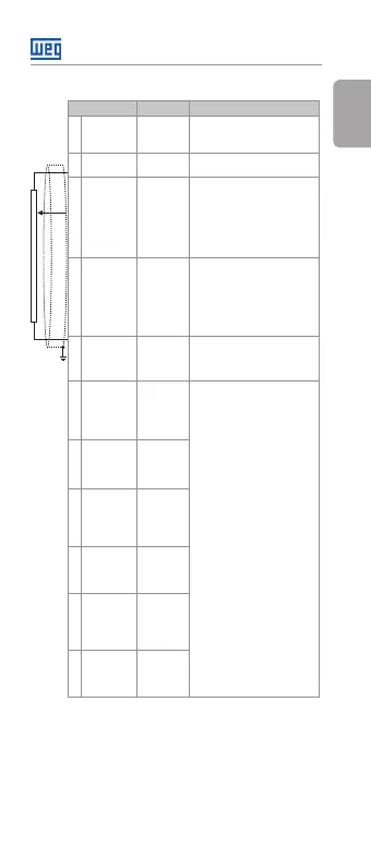
Table 1: Signals of the I/O expansion connector
Connector Description Specifications
6 NTC NTC
Sensor
Input.
NTC 10 K B3435 K.
7 GND Reference
0 V.
Not interconnected to PE.
8 AI1 Analog
Input 1
(voltage).
Isolated voltage input, level:
0 to 10 Vdc.
Resolution: 10 bits.
Impedance: 100 kΩ.
Programmable functions.
Maximum voltage
accepted: 30 Vdc.
9 AI1 Analog
Input 1
(current).
Isolated current input, level
(0 to 20) mA or (4 to 20) mA.
Resolution: 10 bits.
Impedance: 500 Ω.
Programmable functions.
Maximum voltage
accepted: 30 Vdc.
10 + 10 V Reference
+ 10 V for
potentio-
meter.
Power supply: + 10 Vdc.
Maximum capacity: 50 mA.
Tolerance: ±5 %.
11 DO1-RL-C Digital
Output 1
(Common
point of
relay 1).
1 relay with NO contact.
Maximum voltage: 240 Vac.
Maximum current: 0.5 A.
Minimum current: > 1 uA
Programmable functions.
12 DO1-RL-NO Digital
Output 1
(NO point
of relay 1).
13 DO2-RL-C Digital
Output 2
(Common
point of
relay 2).
14 DO2-RL-NO Digital
Output 2
(NO point
of relay 2).
15 DO3-RL-C Digital
Output 3
(Common
point of
relay 3).
16 DO3-RL-NO Digital
Output 3
(NO point
of relay 3).
Counter-
clockwise
≥5 k
Clockwise