Infrared Remote Control and I/O
Expansion Module
English
8 | CFW100
ATTENTION!
For the proper operation of the CFW100
inverter with the CFW100-IOADR module, the
parameters P308, P310, P311 and P312 must
be programmed with the factory settings.
For further details, refer to the programming
manual of the CFW100 V2.0X or up.
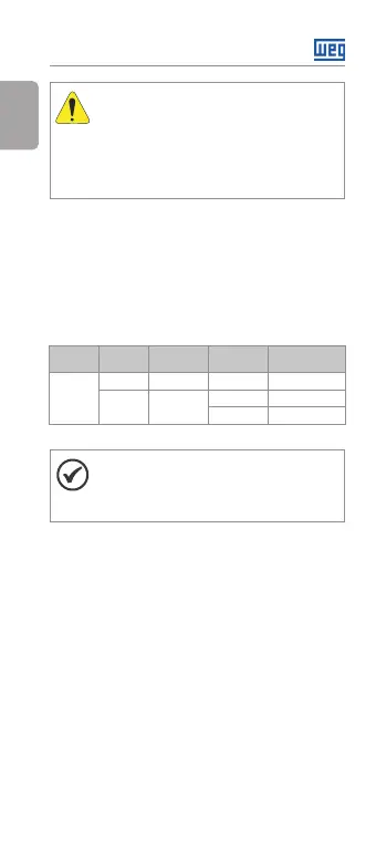
In order to use the analog input with voltage signal,
pin 8 of the I/O expansion connector must be used.
For current signal, pin 9 of the same connector must is
available. Related parameters must also be set as per
Table 2 on page 8.
Table 2: Configurations of connectors to select the type of
analog input signal on the CFW100-IOADR
Input Signal Connector
Signal
Range
Parameter
Setting
AI1
Voltage 8 0 ... 10 V P233 = 0 or 2
Current 9
0 ... 20 mA P233 = 0 or 2
4 ... 20 mA P233 = 1 or 3
NOTA!
The firmware version of the CFW100-IOADR
accessory can be viewed in parameter P024
of the CFW100 inverter.
Information about parameter configuration of the
CFW100 inverter related to the CFW100-IOADR
accessory is presented in Table 3 on page 9.