4
ASSEMBLY
Assembly requires two people. Due to the size
and weight of the training system, assemble it in the
location where it will be used.
•
Place all parts of the training system in a cleared
area and remove the packing materials; do not
dispose of the packing materials until assembly is
completed.
• Before beginning, read each assembly step and
look at each drawing carefully.
• For help identifying small parts used in assembly,
refer to the PART IDENTIFICATION CHART
attached to the centre of this manual.
• During assembly, be sure that all parts are orient-
ed as shown in the drawings.
• Tighten all parts as you attach them, unless
instructed to do otherwise.
THE FOLLOWING TOOLS (NOT INCLUDED) ARE
R
EQUIRED FOR ASSEMBLY:
• two (2) adjustable wrenches
• one (1) phillips screwdriver
• one (1) rubber mallet
• lubricant, such as grease or petroleum jelly,
and soapy water are also required.
To simplify assembly, the following tools are recom-
mended: a socket set, open or closed wrenches, or
ratchet wrenches.
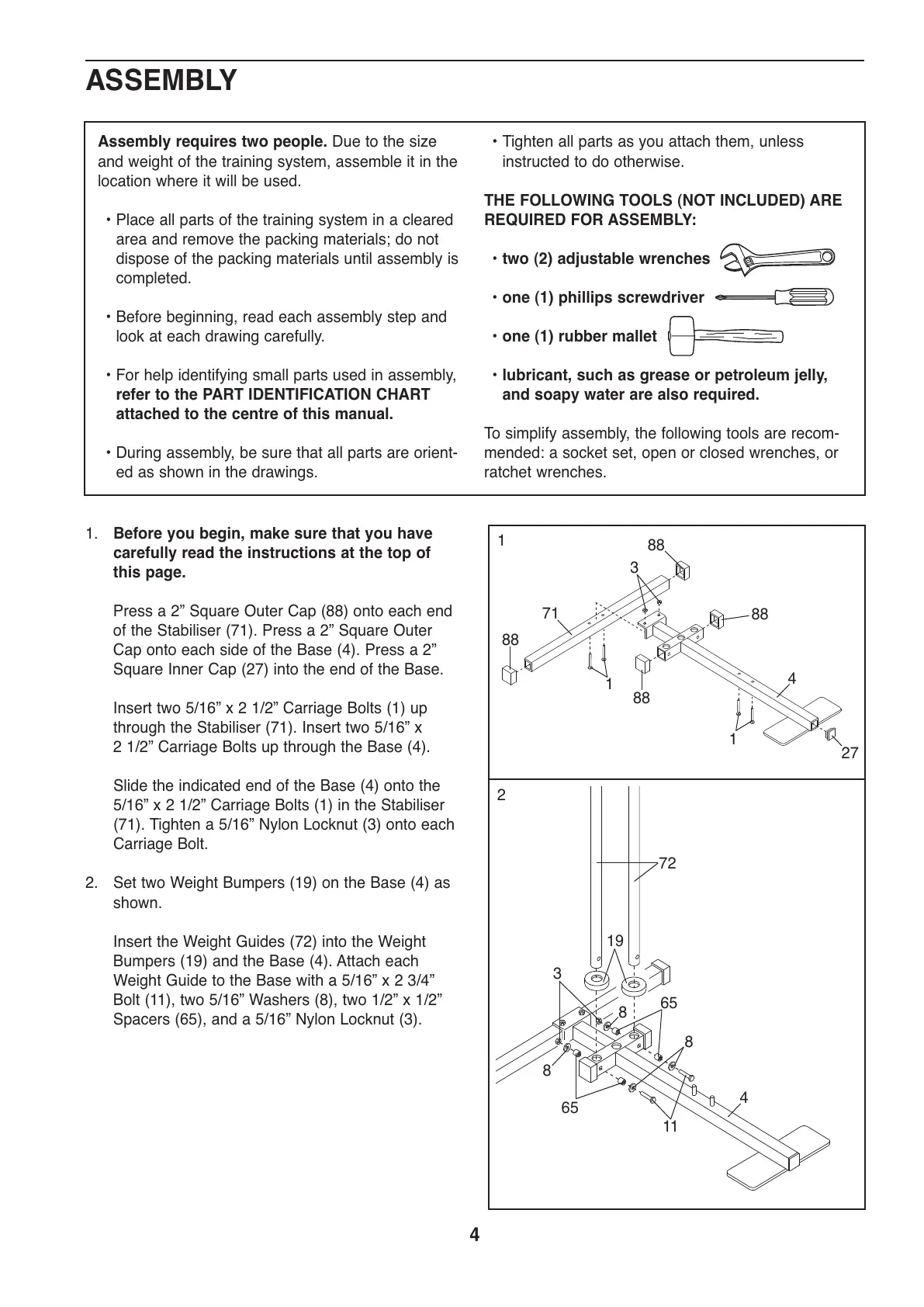
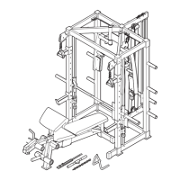
1. Before you begin, make sure that you have
carefully read the instructions at the top of
this page.
Press a 2” Square Outer Cap (88) onto each end
of the Stabiliser (71). Press a 2” Square Outer
Cap onto each side of the Base (4). Press a 2”
Square Inner Cap (27) into the end of the Base.
Insert two 5/16” x 2 1/2” Carriage Bolts (1) up
through the Stabiliser (71). Insert two 5/16” x
2 1/2” Carriage Bolts up through the Base (4).
Slide the indicated end of the Base (4) onto the
5/16” x 2 1/2” Carriage Bolts (1) in the Stabiliser
(71). Tighten a 5/16” Nylon Locknut (3) onto each
Carriage Bolt.
2. Set two Weight Bumpers (19) on the Base (4) as
shown.
Insert the Weight Guides (72) into the Weight
Bumpers (19) and the Base (4). Attach each
Weight Guide to the Base with a 5/16” x 2 3/4”
Bolt (11), two 5/16” Washers (8), two 1/2” x 1/2”
Spacers (65), and a 5/16” Nylon Locknut (3).
1
88
88
88
88
4
1
19
3
8
8
8
11
65
65
72
71
3
1
27
2
4