12
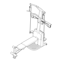
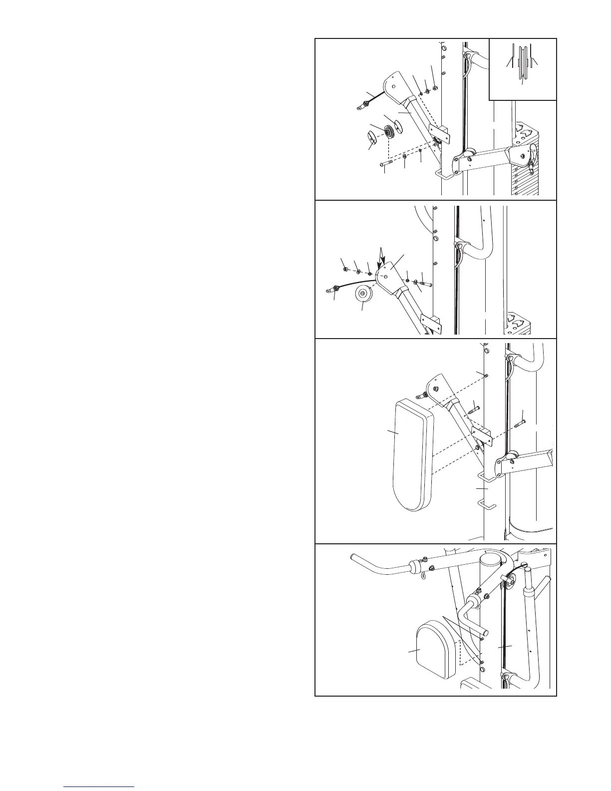
20. Attach a 2 3/4" Pulley (23) to the right Press Arm
(8) with an M10 x 53mm Button Bolt (61), two
M
10 Washers (71), two 5mm Spacers (25), two
Finger Guards (27), and an M10 Nylon Locknut
(73). See the inset drawing. Orient the Finger
Guards and Pulley as shown. Make sure the
Press Arm Cable (30) is in the groove of the
Pulley.
21. Make sure the Press Arm Cable (30) is routed
under the indicated welded rods.
Attach a “V”-pulley (22) to the Swivel Arm (16)
with an M10 x 64mm Button Bolt (75), two M10
Washers (71), two 5mm Spacers (25), and an
M10 Nylon Locknut (73).
20
21
7
3
3
0
71
71
61
8
75
71
16
71
73
25
25
30
22
25
27
23
2
7
25
Welded
Rods
2
7
27
23
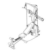
22. Attach the Backrest (18) to the Upright (3) with
two M6 x 25mm Screws (60) and the indicated
M6 x 127mm Screw (79).
22
79
60
60
18
3
23.
Attach the Headrest (90) to the Upright (3) with
the two indicated M6 x 127mm Screws (79).
23
90
3
79
 Loading...