FRAME ASSEMBLY
Locate and open the parts bags labeled "FRAME
ASSEMBLY 1" and "FRAME ASSEMBLY 2."
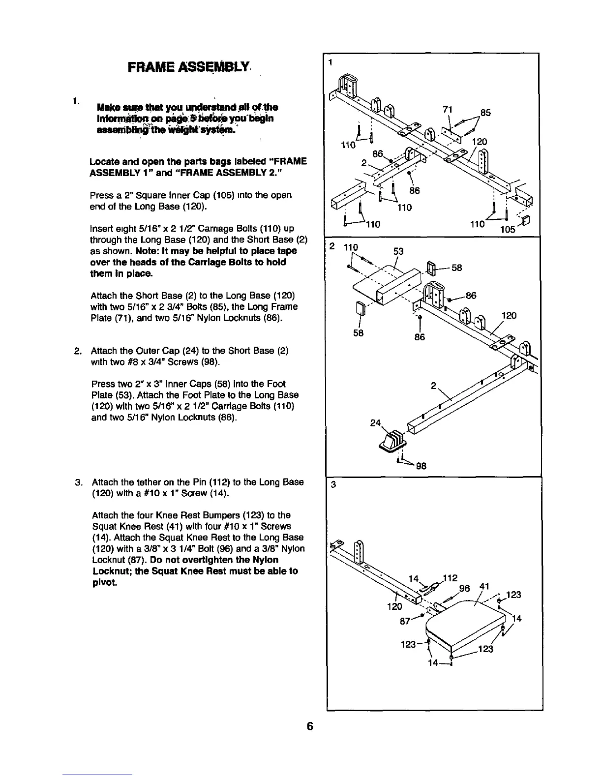
Press a 2" Square Inner Cap (105) intothe open
end of the Long Base (120).
Inserteight 5/16" x 2 1/2"Carnage Bolts(110) up
throughthe Long Base (120) and the Short Base (2)
as shown. Note: It may be helpful to place tape
over the heads of the Carriage Bolts to hold
them In place.
Attach the Short Base (2) to the Long Base (120)
with two 5/16" x 2 3/4" Bolts(85), the Long Frame
Plate (71), and two 5116"Nylon Locknuts(86).
2. Attach the Outer Cap (24) to the Short Base (2)
wtthtwo #8 x 3/4" Screws (98).
Press two 2" x 3" Inner Caps (58) intothe Foot
Plate (53). Attach the Foot Plate tothe Long Base
(120) with two 5/16" x 2 112"Carriage Bolts (110)
and two 5116"Nylon Locknuts(86).
3.
Attach the tether on the Pin (112) to the Long Base
(120) witha #10 x 1"Screw (14).
Attach the four Knee Rest Bumpers(123) tothe
Squat Knee Rest (41) with four #10 x 1"Screws
(14). Attachthe Squat Knee Rest tothe Long Base
(120) with a 3/8" x 3 1/4" Bolt(96) and a 3/8" Nylon
Locknut(87). Do not overtlghten the Nylon
Locknut; the Squat Knee Rest must be able to
pivot.
3
86
110
110
110 53
58
71 B5
12O
110
1
120
86
2\
24
41
6