18
W
EIGHT PRESS ARM BUTTERFLY ARM LEG LEVER HIGH PULLEY LOW PULLEY
PLATES (lbs.) (lbs.) (lbs.) (lbs.) (lbs.)
Top 20 15 30 14 24
1 45 33 50 28 54
2 70 43 70 44 82
3 99 55 95 60 115
4 128 67 115 72 147
5 153 75 133 90 175
6 184 90 150 103 209
7 210 100 168 140 250
8 237 110 185 157 280
9 260 120 205 175 300
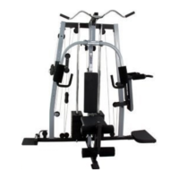
This chart shows the approximate weight resistance at each station. “Top” refers to the 6.5-lb. (2.95 kg) top
weight. The other numbers refer to the 12.5-lb. (5.67 kg) weight plates. Weight resistance shown for the butterfly
a
rm station is for each butterfly arm.
Note: The actual resistance at each weight station may vary due to differences in individual weight plates, as
well as friction between the cables, pulleys, and weight guides.
1 lb. = 0.454 kg
WEIGHT RESISTANCE CHART
7
5. Press a 50mm Square Inner Cap (55) into the
end of the Top Frame (10). Press two 45mm
Square Inner Caps (56) into the ends of the
crossbar on the Top Frame. Press two Round
Inner Caps (59) into the top of the crossbar.
Attach the Top Frame (10) to the Front Upright (4)
and the Rear Upright (5) with four M8 x 68mm
Bolts (73), two Small Support Plates (93), and
four M8 Nylon Locknuts (83).
4. Press a 25mm Square Inner Cap (53) into the
Front Upright (4).
Slide the Front Upright (4) onto the M8 x 63mm
Carriage Bolts (65) in the Base (2). Hand tighten
two M8 Nylon Locknuts (83) onto the Carriage
Bolts. Do not tighten the Locknuts yet.
4
3
3. Slide the nine Weights (22) onto the Weight
Guides (9). Make sure that all of the Weights
a
re turned so the large pin grooves are on the
bottom of the Weights and on the front of the
w
eight stack.
Press the Weight Tube Bumper (27) into the end
of the Weight Tube (26). Insert the Weight Tube
into the stack of Weights (22).
Lubricate the insides of the holes in the Top
Weight (24) with grease. Slide the Top Weight
onto the Weight Guides (9).
Make sure that the
pin grooves are on the bottom of the Top
Weight. Make sure that the pins on the Weight
Tube (26) rest in the pin grooves in the Top
Weight.
5
L
ubricate
Pin
Groove
Pin
Groove
Pin
24
9
26
22
27
56
55
10
59
73
73
4
53
83
65
2
93
93
56
83
83
4
5
Crossbar