- 9 -
Wiring the Redundant Power Inputs
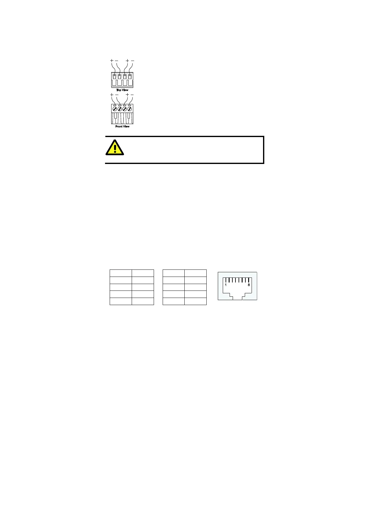
The top two contacts and the bottom two contacts of the 4-contact terminal block
connector on the Ethernet Switch’s top panel are used for the Ethernet Switch’s
two AC/DC inputs. Top and front views of one of the terminal block connectors
are shown here.
STEP 1: Insert the negative/positive AC/DC wires into the
V-/V+ terminals.
STEP 2: To keep the AC/DC wires from pulling loose, use a
small flat-blade screwdriver to tighten the wire-clamp
screws on the front of the terminal block connector.
STEP 3: Insert the plastic terminal block connector prongs
into the terminal block receptor, which is located on Ethernet
Switch’s top panel.
ATTENTION
Before connecting the Ethernet Switch to the AC/DC power inputs,
make sure the AC/DC power source voltage is stable.
Communication Connections
The IE-SW-BL05 models have 4 or 5 10/100BaseT(X) Ethernet ports, and 1 or 0
(zero) 100 BaseFX multi/single-mode (SC/ST-type connector) fiber ports. The
IE-SW-BL08 models have 6, 7 or 8 10/100BaseT(X) Ethernet ports, and 2, 1 or
0 (zero) 100 BaseFX multi/single-mode (SC/ST-type connector) fiber ports.
10/100BaseT(X) Ethernet Port Connection
The 10/100BaseT(X) ports located on the Ethernet Switch’s front panel are used
to connect to Ethernet-enabled devices. Below we show pinouts for both MDI
(NIC-type) ports and MDI-X (HUB/Switch-type) ports, and also show cable
wiring diagrams for straight-through and cross-over Ethernet cables.
 Loading...