GOLD GV WGOLD GV W
GOLD GV WGOLD GV W
GOLD GV W
ater Boiler — Series 4ater Boiler — Series 4
ater Boiler — Series 4ater Boiler — Series 4
ater Boiler — Series 4
Part number 550-141-856/070330
Water piping — all systemsIIId
Zoning with
circulators
The GV internal system circulator cannot be removed
from the boiler for use as one of the zone circulators. It
must remain as shipped from the factory to allow proper
flow control inside the boiler. You will need a circulator
for each zone.
Install and wire a separate relay for each zone circulator.
Additional
components
If installation is to comply with ASME or Canadian requirements, an additional high
temperature limit
is needed.
• Purchase and install in system supply piping between boiler and isolation valve.
• Wire the second limit control in series with the boiler limit control.
• Set the second limit control at least 20 °F above the boiler limit control setting (maximum
setting 240 °F).
A low water cutoff device is required when boiler is installed above radiation level or by
certain state or local codes or insurance companies. Use low water cutoff designed for water
installations. Electrode probe-type is recommended. Purchase and install in tee in supply
piping above boiler.
If boiler is connected to heating coils located in air handling units where they
can be exposed to refrigerated air, use flow control valves or other automatic
means to prevent gravity circulation during cooling cycle. Circulation of
cold water through the boiler could result in damage to the heat exchanger,
causing possible severe personal injury, death or substantial property damage.
Do not remove either of the GV internal pumps for use elsewhere in the
system. Both pumps are required for proper operation. Removing a pump
will cause the boiler to malfunction. Substantial property damage could
result.
Never install another pump in series with the GV boiler. Forced flow
can cause improper operation of the boiler controls. Substantial property
damage could result.
Zoning with
zone valves
Each zone in the piping diagrams in this section is shown with an isolation valve on each
side. Substitute a memory-stop valve for one of these in each zone in order to use the memory-
stop valve for balancing flow as well as isolation.
Provide a separate 24-volt transformer to power the zone valves. Size the transformer to
handle the total rated load of all connected zone valves.
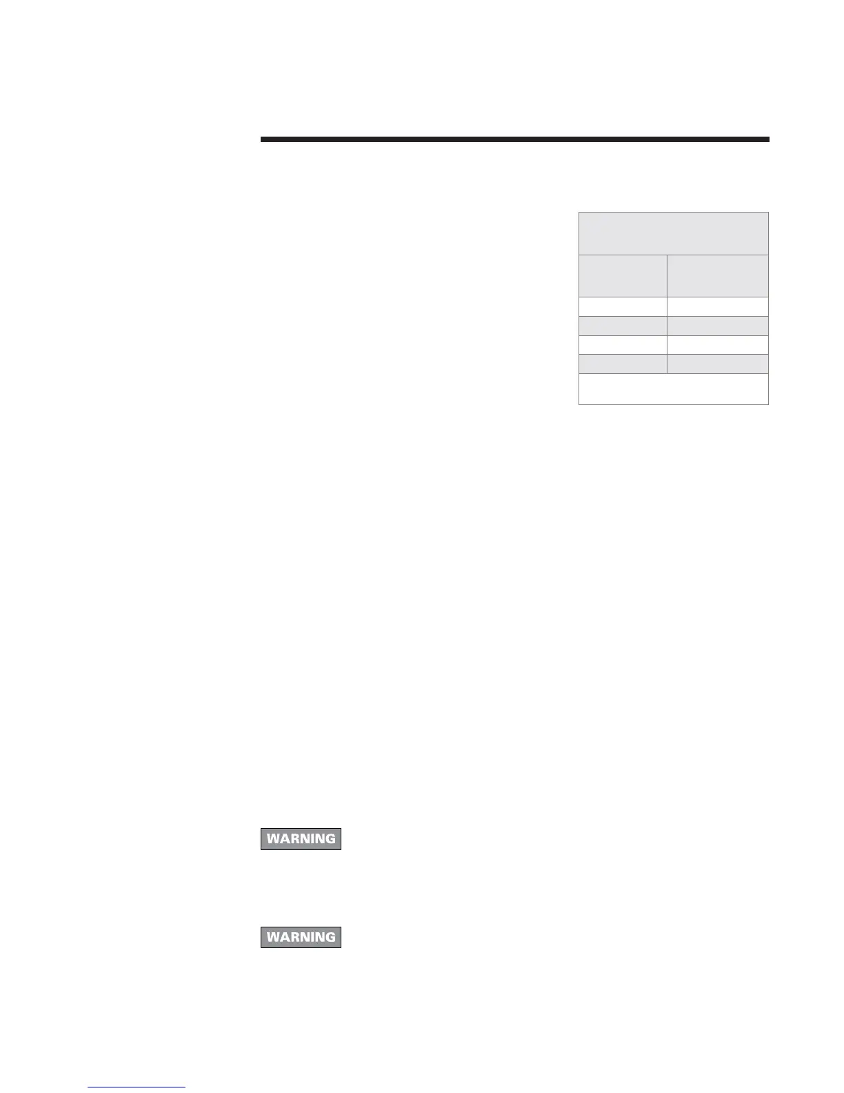
Alternate primary
manifold sizing
Boiler model
number
Suggested
pipe size
GV-3 1"
GV-4 1"
GV-5 1¼"
GV-6 1¼"
Note: GV-5 and GV-6 may require 1¼"
or larger piping off of boiler.
 Loading...