Revised 4/11/08 2-9
Installation
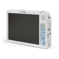
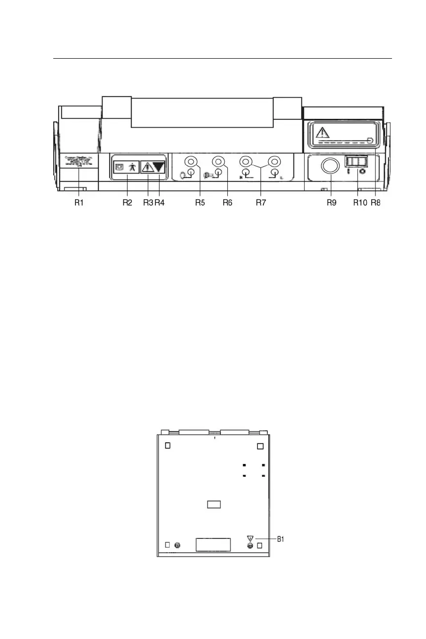
Rear and Bottom Panel Labels and Connectors
Figure 9: Rear and bottom panel labels and connectors.
R1: Company name, address, model, serial number and country of origin.
R2: Symbol denotes a Type B, Class II product per IEC 878 as referenced in IEC 60601-1.
R3: Symbol denotes Attention, consult accompanying documents.
R4: Symbol indicates a service adjustment part that is intended for service personnel use only.
R5: Connector for handswitch. Input impedance (47 K ohm pulls up to 5 volts).
R6: Connector for contralateral insert phone. Function not available.
R7: Connectors for right and left earphone. 130 ohm, 2.50 volts rms maximum open circuit.
R8: Label describing low input voltage and current from desktop power supply.
R9: Power Input Jack. 5-pin DIN connector for external desktop power supply.
R10: Power Switch with ON/OFF indicators.
NOTE: There is a symbol on the bottom panel (marked B1 in Figure 10) that indicates entry
by qualified service personnel only.
Figure 10: Bottom panel.
 Loading...