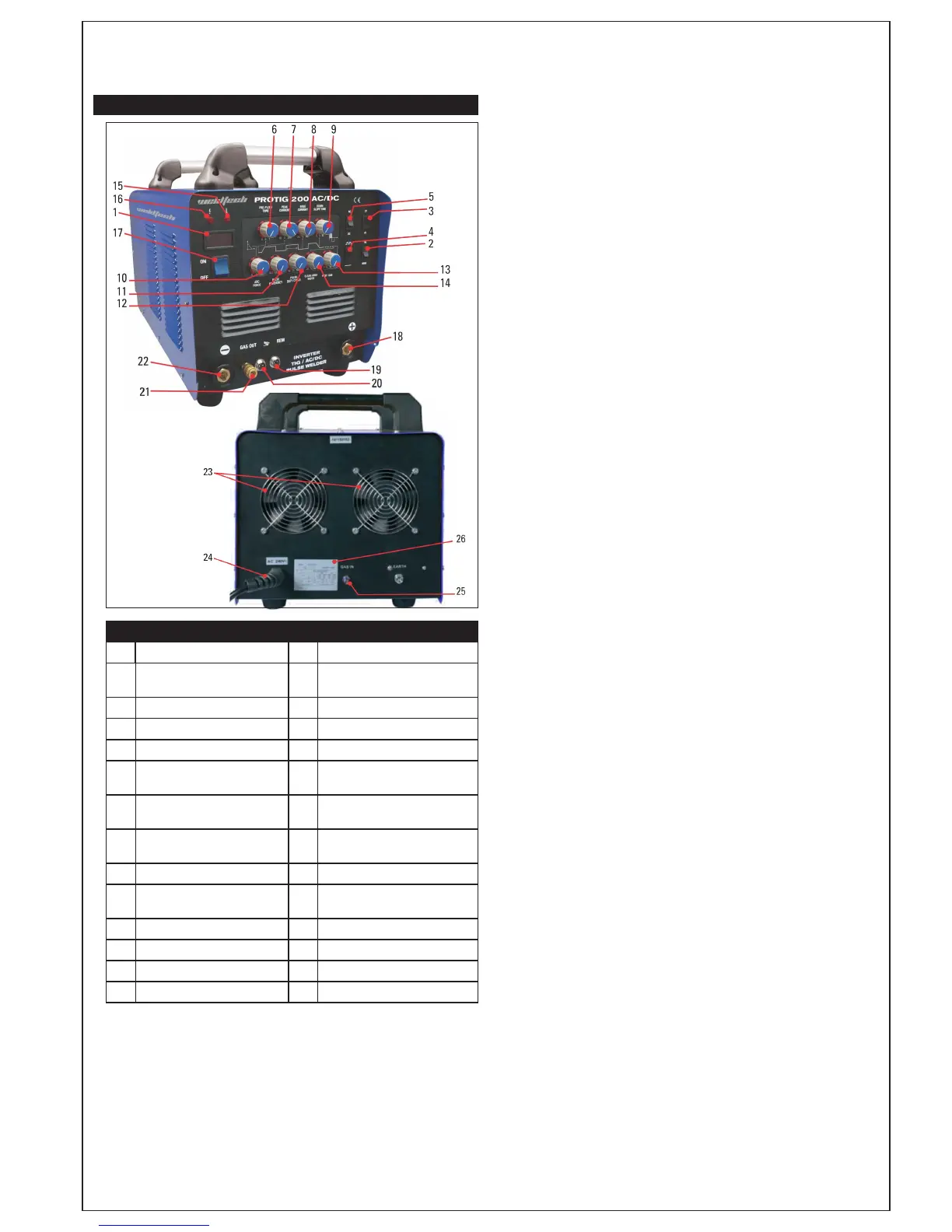
Function Reference Table
No. Description No. Description
1 LCD Current Meter 14
Clean Area Width/AC Balance
Adjustment
2 TIG/MMA Mode Switch 15
Mains Power On Indicator Lamp
3 2T/4T Trigger Mode Switch 16
Overload Indicator Lamp
4 Pulse Welding Mode Switch 17 Mains Power Switch
5 AC/DC Output Mode Switch 18
Positive (+) Welding Power
Output Terminal
6 Gas Pre-Flow Time Adjustment 19
Remote Current Control
Connection Socket
7 Peak Current Adjustment 20
Torch Switch Remote Connec-
tion Socket
8 Base Current Adjustment 21 Shielding Gas Outlet
9 Down Slope Adjustment 22
Negative (-) Welding Power
Output Terminal
10 ARC Force Adjustment 23 Cooling Fans
11 Pulse Frequency Adjustment 24 Mains Power Input Cable
12 Pulse Duty Adjustment 25 Gas Inlet Connector
13 Gas After-Flow Adjustment 26 Data Plate
4T/2T Trigger Control Switch (Ref. 3) - This switch controls the trigger mode for
the TIG torch trigger. 2T mode the trigger is depressed and held on to activate
the welding circuit, when the trigger is released, the welding circuit stops. 4T
is known as ’latching’ mode. The trigger is depressed once and released to
activate the welding circuit, depressed and released again to stop the welding
circuit. This function is useful for longer welds as the trigger is not required to
be held on continuously.
AC/DC Output Mode Switch (Ref. 5) - DC (direct current) output mode is
suitable for TIG welding metals such as mild steel and stainless steel, copper
and titanium. TIG welding reactive metals such as aluminium, magnesium and
zinc requires AC (alternating current) output.
When reactive metals are exposed to air they form an oxide layer that
insulates the base metal and prevents welding current flowing, it also
contaminates the weld area. Reverse current flow is required to break
through/ clean off this oxide layer so that welding can take place, while the
current flow during the positive cycle does the majority of the heating of the
weld pool area.
Pulse Welding Mode (Ref. 4) - Switches the welding output between a higher
and lower current output in a cyclic manner. When used correctly this function
provides greater weld penetration for less work heat input and greater control
of the weld pool.
Gas Pre-flow Time Adjustment (Ref. 6) - When the trigger is depressed, this
adjustment controls how long the gas flows before the arc is initiated. This is
necessary when purging the start of the weld area of any atmospheric gases
before the arc starts.
Peak Current Adjustment (Ref. 7) - Provides adjustment for the output current.
Base Current Adjustment (Ref. 8) - When using pulse mode, this adjustment
sets the current for the low/base pulse with respect to the peak current.
This is a percentage adjustment. E.g with the peak current set at 160A and the
base current adjustment set at 50%, the base current pulse will be 80A. (160A
x 50%). The basic theory for setting the base current using pulse mode is that
the base current should be sufficient to maintain the existing molten weld pool,
while the peak current is sufficient to melt new metal in order to move/ expand
the molten weld pool.
Down Slope Adjustment (Ref. 9) - When the trigger is released, this adjustment
causes the current to gradually decrease from the peak amps to 0 over the set
time (in seconds). To turn the function off, set the adjustment to 0. This function
is useful to prevent an uneven finish to the weld or a ‘crater’ forming when the
weld current stops abruptly.
Arc Force Adjustment (Ref. 10) - this adjustment impacts MMA, and has little
effect in TIG mode. The adjustment changes the characteristic of the volts/amp
relationship during welding. When MMA welding, output current is constant
as set, while the voltage changes with the arc length (the distance from the
electrode to the work piece). A shorter arc length will give a narrower weld
with more penetration, while a longer arc length gives a wider ‘colder’ weld
pool. A shorter arc can be unstable if the voltage gets too low. Increased arc
force adjustment will boost the welding voltage when it drops with a shorter
arc, giving a more penetrating arc when used with short arc length.
A basic rule of thumb is increased arc force will give an arc characteristic that
feels more penetrating and tight, while decrease in arc force will give a softer,
less focused arc.
Pulse Frequency Adjustment (Ref. 11) - Pulse mode sets the rate that the
output current switches between high and low. Increased pulse frequency
will have the effect of making the arc more tightly focused, which is useful for
fine stainless work and similar. A slow pulse rate can be used to help move the
weld pool along, this technique is useful with welding Aluminium, as molten
Aluminium forms a more viscous ‘sticky’ weld pool.
Pulse Duty Adjustment (Ref. 12) - This adjustment sets the time proportion as
a percentage between the peak current and base current when using pulse
mode. Neutral setting is 50%, the time period of the peak current and base
current pulse is equal. Higher pulse duty setting will give greater heat input,
while lower pulse duty will have the opposite effect.
Clean Width Area/ AC Balance Adjustment (Ref. 14) - Sets the balance
between the forward and reverse current cycles when welding in AC output
mode. The reverse part of the cycle gives the ‘cleaning’ effect on the weld
material, while the forward cycle melts the weld material. Neutral setting is
50%. Increased reverse cycle bias will give greater cleaning effect, less weld
penetration and more heat in the torch tungsten, reducing the output current
that can be used for a given tungsten size. Increased forward cycle bias will
give the opposite effect, less cleaning effect, greater weld penetration and
less heat in the tungsten. Ideally for maximum effectiveness, the clean width/
AC balance should be set with as much forward cycle bias as possible, while
still maintaining a sufficient level of oxidisation removal for a contamination
free weld pool. The cleaner the metal, the more effective it is to weld.
Gas After-flow Adjustment (Ref. 13) - This adjustment sets the period of time
that the gas control valve stays open. It is important for TIG welding that that
the weld pool and the torch tungsten remain protected from atmospheric
contamination by the shielding gas until they have cooled sufficiently.
The tungsten should be able to be touched by hand before the shielding gas
stops flowing.
Remote Current Control Connection Socket (Ref. 19) - For connection of a
torch with external amperage control capability. Refer consumables and
accessories section for a suitable upgrade torch part number.
Overload Indicator Lamp (Ref. 16) - Lights when duty cycle is exceeded and
thermal protection is activated. When activated, welding output will
be disabled until machines cools sufficiently and overload indicator lamp
goes out.
KNOW YOUR WELDER
 Loading...