2.1 Before You Begin
After unpacking the unit, check the equipment for compliance and any damage that may have occurred during shipment.
Immediately contact a Welker representative if you received damaged equipment.
When sealing fittings with PTFE tape, refer to the proper sealing instructions for the brand used.
2.2 Installing the Unit
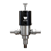
Note the inLoop™ ACE is bidirectional.
1. Depressurize the fast loop.
The fast loop must be depressurized prior to installing and removing the unit.
2. If the inLoop™ ACE has an FNPT or VCO process connection, continue to step 3. If the inLoop™ ACE has a flanged
process connection, proceed to step 6.
FNPT or VCOProcess Connection
3.
Using 1" tubing or pipe, connect from the fast loop to the process inlet on the inLoop™ ACE (Figure 2, Figure 3, Figure 4,
or Figure 5).
4.
Using 1" tubing or pipe, connect from the process outlet on the inLoop™ ACE to the fast loop (Figure 2, Figure 3, Figure
4, or Figure 5).
5. Proceed to step 15.
Flanged Process Connection
6.
Position an appropriately sized gasket on one mating flange connection (Figure 6).
7. Install one flange of the inLoop™ ACE to the first mating flange connection.
8. Following a cross-bolting sequence, install bolts and nuts to the flanges.
9. Tighten all bolts to the appropriate torque.
10.
Position an appropriately sized gasket on the other mating flange connection (Figure 6).
11. Install the other flange of the inLoop™ ACE to the second mating flange connection.
12. Following a cross-bolting sequence, install bolts and nuts to the flanges.
13. Tighten all bolts to the appropriate torque.
14. Continue to step 15.
SECTION 2: INSTALLATION&OPERATION
11
IOM-224 MODEL: INLOOP™ ACE REV: A 13839 West Bellfort Street, Sugar Land, TX 77498 welker.com Service Department 281.491.2331