Completing Installation
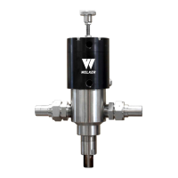
15. Using appropriately sized tubing, connect from the sample outlet to an appropriate customer-supplied sample
container, such as a Welker TCCTransportable Crude Oil Container for crude oil or a Welker Constant Pressure Cylinder
for light liquids (Figure 2, Figure 3, Figure 4, Figure 5, or Figure 6 and Table 2).
If the inLoop™ ACE is not equipped with a valve on the sample outlet, Welker recommends installing a valve to the sample
outlet. This will be outlet valve A.
Table 2: Recommended Tubing Size – Sample Container
Product Sampled Tubing Size
Light Liquids or Light Crude Oil Minimum ¼"
Medium or Heavy Crude Oil Minimum ³⁄₈"
Customer-supplied tubing must slope downward from the inLoop™ ACE to the sample container.
16. Using appropriately sized tubing, connect from the normally open port on the solenoid to port A on the motor housing
(Figure 2, Figure 3, Figure 4, Figure 5, or Figure 6 and Table 3). Using appropriately sized tubing, connect from the
normally closed port on the solenoid to port B on the motor housing (Figure 2, Figure 3, Figure 4, Figure 5, or Figure 6
and Table 3).
Table 3: Recommended Tubing Size – Motor Operation
Utility Supply for Motor Operation Tubing Size
Pneumatics Minimum ¼"
Hydraulics Minimum ³⁄₈"
17.
If applicable, ensure that outlet valve A is closed (Figure 3 or Figure 4).
18.
If applicable, ensure that the optional external sand relief has been set (Figure 3 or Figure 4).
19. If applicable, ensure that the customer constant pressure cylinder has been pre-charged and that all cylinder valves are
closed.
20. Pressurize the fast loop.
21. Check for leaks and repair as necessary.
12
IOM-224 MODEL: INLOOP™ ACE REV: A 13839 West Bellfort Street, Sugar Land, TX 77498 welker.com Service Department 281.491.2331