22
IOM-224 MODEL: INLOOP™ ACE REV: A 13839 West Bellfort Street, Sugar Land, TX 77498 welker.com Service Department 281.491.2331
Collection Head Assembly Maintenance
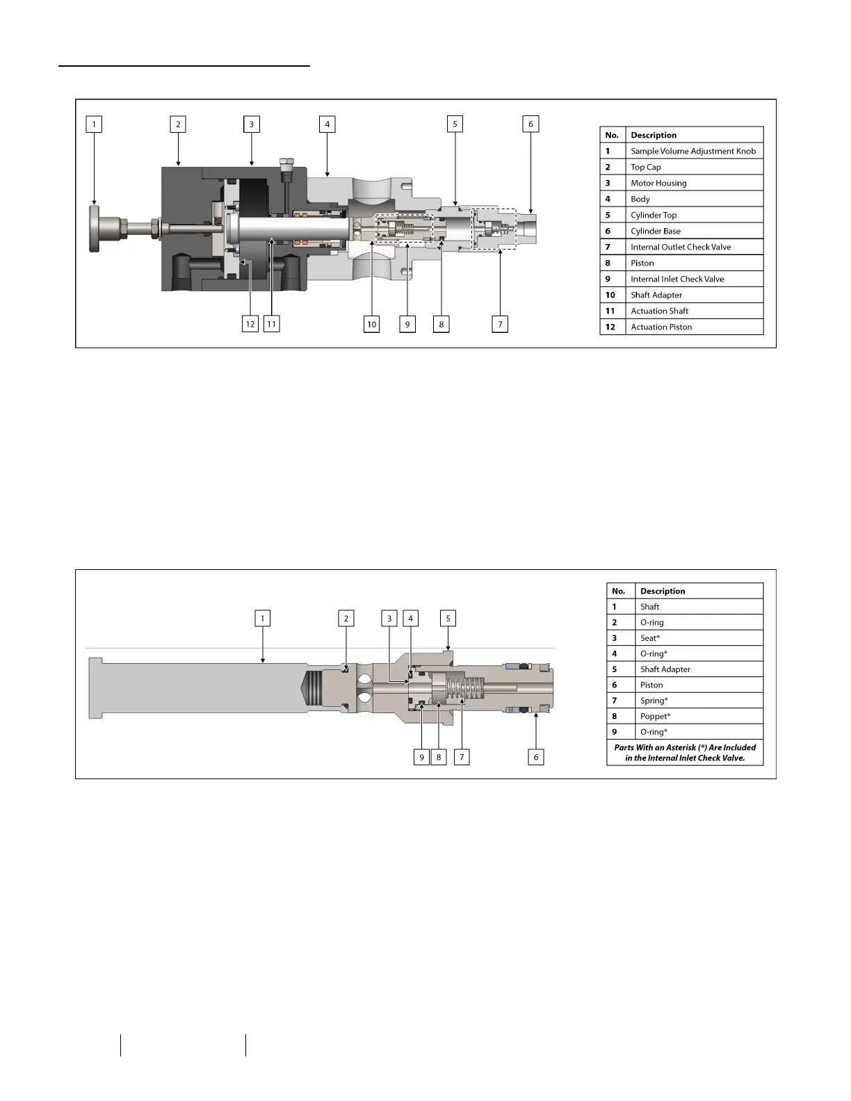
Figure 13: inLoop™ ACE Disassembly Diagram
17. Unscrew the cylinder base from the cylinder top and set the cylinder base aside. Note the internal outlet check valve
will be removed at this time.
18. Unscrew the cylinder top from the body.
19. Unscrew the body from the motor housing. Note the actuation shaft assembly will be exposed.
20. While holding the actuation shaft with a wrench at the wrench flats, use a second wrench to unscrew the shaft adapter
and piston. Note the internal inlet check valve will be exposed.
Internal Inlet Check Valve
Figure 14: Internal Inlet Check Valve Diagram
21. Unscrew the piston from the shaft adapter.
22. Unscrew the shaft adapter from the shaft.
23. Replace the O-ring on the shaft adapter, and then screw the shaft adapter back onto the shaft.
24. Remove the seat, poppet, and spring from the piston.
25. Examine the seat for damage or wear. Replace as necessary.
26. As necessary, replace the O-rings on the seat.
27. Examine the spring for damage or wear. Replace as necessary.
28. Examine the poppet for damage or wear. Replace as necessary.