7
ASSEMBLY
MOUNTING THE LATHE ON THE BENCHTOP
Measure and mark three hole centers as shown in Figure A. Drill
clearance holes through the bench top and position the lathe in place.
Attach it securely with bolts (minimum of one inch) and washers (not
included) from the underside of the bench top into the tapped holes
in the bottom of the lathe’s frame. The hole thread is M8-1.25.
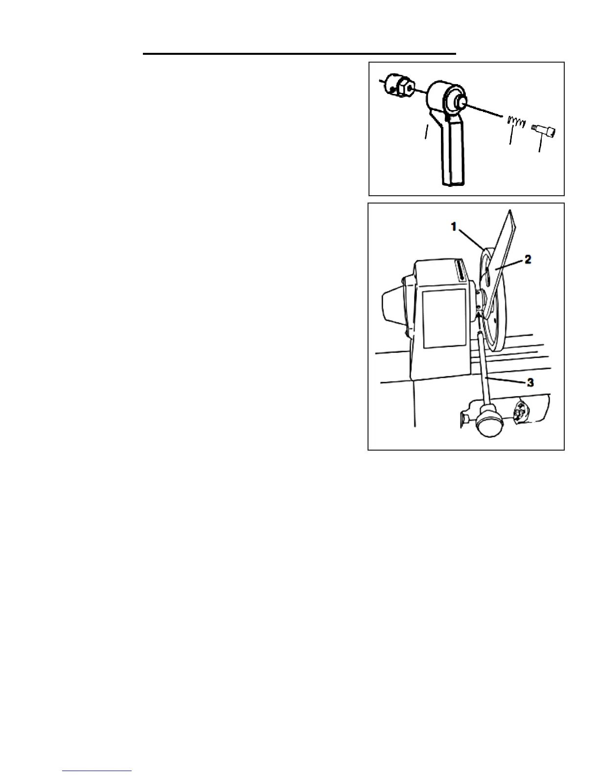
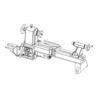
SPRING LOADED LOCK LEVERS
Check to make sure that the lock levers for the tailstock quill and the
tool rest have not come loose. If they have, reassemble them with the
shoulder screw (Fig. B - 1) passing through the spring (Fig. B - 2) and
the handle (Fig. B - 3).
These spring-loaded handles are designed to minimize interference
with other parts of the lathe. To operate, turn the handle clockwise to
tighten or counterclockwise to loosen. Pull the handle outwards to re-
position it as needed, then allow it to spring back into position before
tightening or loosening.
INSTALLING AND REMOVING THE FACE PLATE
1. Thread the faceplate (Fig. C - 1) onto the end of the headstock
quill and hand tighten.
2. Place the wrench (Fig. C - 2) over the flats on the faceplate.
Note: Since the headstock quill is belt driven, it will turn freely if not
held stationary while the faceplate is being tightened or loosened.
Fig. B
Fig. C
3. Insert the tip of the knockout rod (Fig. C - 3) into one of the slots in the side of the headstock quill.
4. Grip the knockout rod firmly while turning the wrench to either tighten or loosen the faceplate.
5. Remove the knockout rod and wrench. If the faceplate is being removed, continue turning it until it comes off
the quill thread.
1
2
3