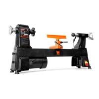
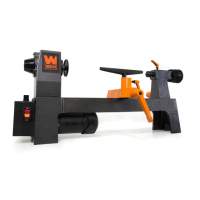
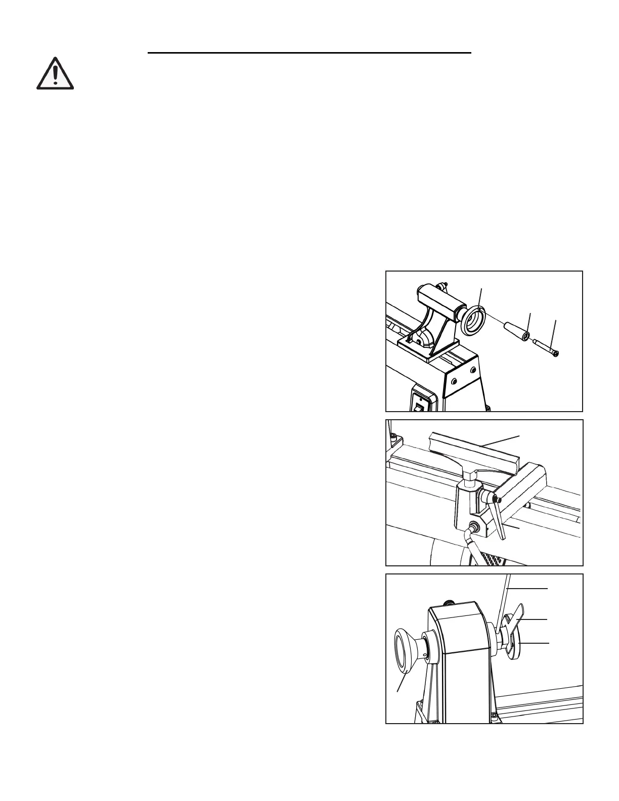
INSTALLING THE HANDLE (Fig. A)
1. Insert the handle screw (Fig. A - 1) through the handle (Fig. A - 2)
and into the hole of the handwheel (Fig. A - 3).
2. Tighten the handle screw using a flathead screwdriver (not includ-
ed).
INSTALLING THE TOOL REST (Fig. B)
1. Loosen the locking handle (Fig. B - 1) and insert the tool rest (Fig.
B - 2) into the tool rest base.
2. Adjust the tool rest height up or down to the desired position and
then tighten the locking handle (Fig. B - 1).
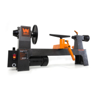
INSTALLING/REMOVING THE FACE PLATE (Fig. C)
1. Mount the face plate (Fig. C - 1) onto the spindle by screwing it
clockwise as far as it will go onto the spindle threads.
2. Then insert the knockout rod (Fig. C - 2) into the hole to lock the
spindle and use the wrench (Fig. C - 3) to fully tighten the face plate.
To remove the face plate, insert the knockout rod into the hole and
use the wrench to loosen the face plate.
ASSEMBLY
WARNING: To prevent injury from accidental operation, make sure the tool is switched OFF and un-
plugged from the power source before assembling or making any adjustments.
Fig. A
Fig. B
1
1
1
2
3
1
2
2
3
9
Tool Rest
REMOVING THE ANTI-RUST GREASE
The lathe bed and centers have been coated with grease to prevent them from rusting.
1. Remove the excess oil and grease by wiping it off with a clean cloth.
2. Remove any residue with a rag moistened with acetone, kerosene, or other removal agent. Wear gloves to pro-
tect your skin. Do not use gasoline, or cellulose-based solvents such as paint thinner or lacquer thinner, as these
will damage the painted surfaces.
3. Apply a light coat of good-quality paste wax to the surfaces to guard against rust and corrosion.
 Loading...