14
ASSEMBLY AND ADJUSTMENTS
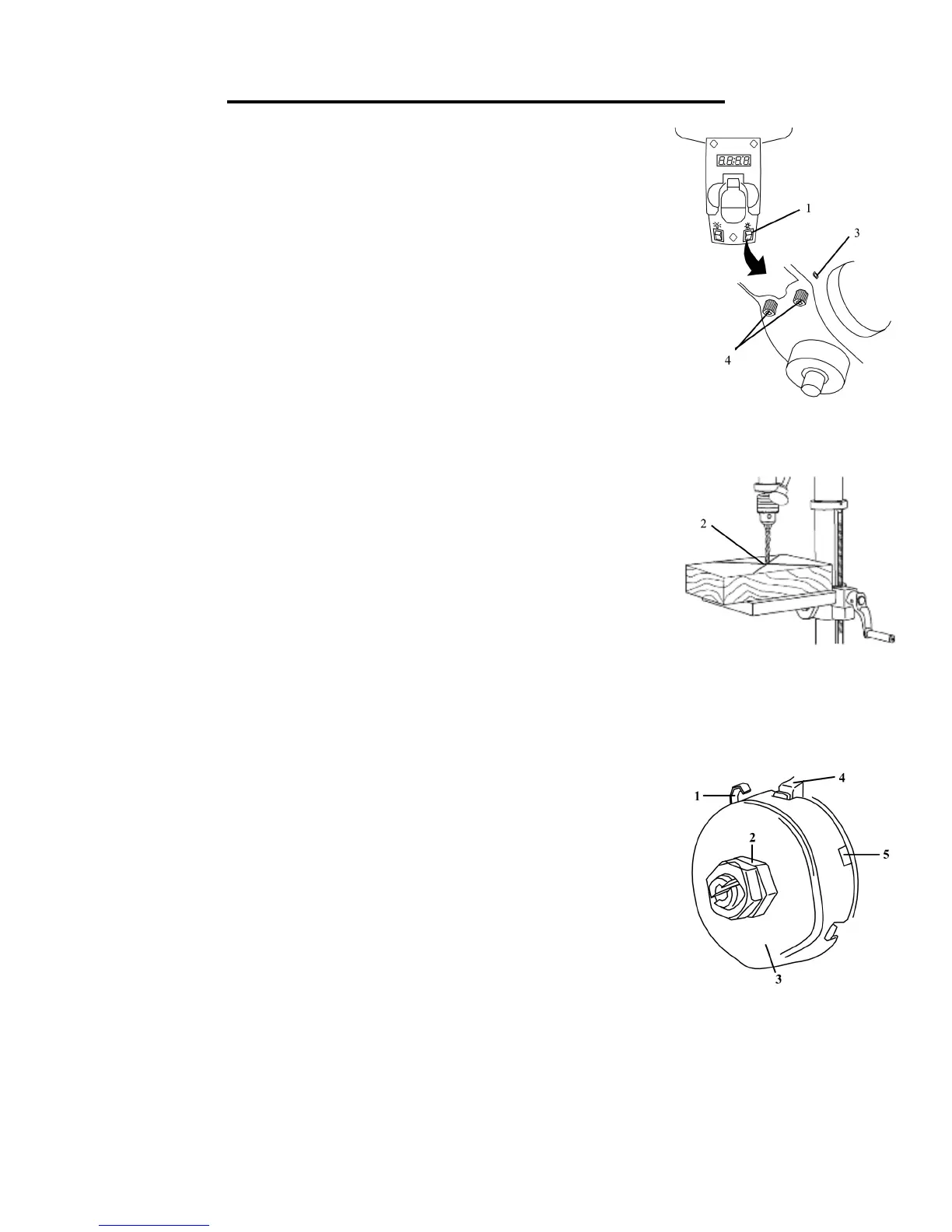
ADJUSTING THE LASER (Fig. 15 and 16)
WARNING: Do not stare directly at the laser beam. Please observe all safety
rules.
• Never aim the beam at a person or an object other than the workpiece.
• Do not project the laser beam into the eyes of others.
• Always make sure the laser beam is aimed at a workpiece that does not
possess reective surfaces, as the laser beam could project into your eyes or
the eyes of others.
1. Place a workpiece on the table.
2. Turn the laser switch (1) to the ON position.
3. Lower the drill bit to meet the workpiece (2). The two laser lines should cross
where the drill meets the workpiece.
4. If the laser needs to be adjusted:
a. Using a 3 mm hex key, turn the laser adjustment set screws (3) counter-
clockwise.
b. Rotate the laser light housing (4) until the two laser lines intersect where
the drill meets the workpiece. DO NOT stare directly at the laser lines.
5. Re-tighten the adjustment set screws (3).
SPINDLE RETURN SPRING (Fig. 17)
The spindle is equipped with an auto-return mechanism. The main components
are a spring and a notched housing. The spring was properly adjusted at the factory
and should not be readjusted unless absolutely necessary.
1. Unplug the drill press.
2. Place a screwdriver into the loop (1) to hold the spring in place.
3. Loosen the two housing nuts (2) approximately 1/4” (6 mm). Do not remove the
nuts from the threaded shaft. Do not allow the spring or spring housing to slip out of
control.
4. While firmly holding the spring housing (3), carefully pull the spring housing out
until it clears the raised notch (4).
5. Turn the housing so that the next notch (5) is engaged with the raised notch (4).
• To increase the spindle return tension, turn the spring housing counter-clockwise.
• To decrease the tension, turn the spring housing clockwise.
6. Tighten the two housing nuts. Do not overtighten the two nuts. If the nuts are tightened too much, the move-
ment of the spindle and feed handles will become sluggish.
Fig. 15
Fig. 16
Fig. 17
 Loading...