Do you have a question about the Wen 5500 and is the answer not in the manual?
Remove the two P2 head screws securing the solenoid and the 14mm hex head bolt from the carburetor bowl.
Separate the bowl from the bottom of the carburetor and remove the float by taking out its pivot pin.
Remove the jet from the carburetor's center stem using a flat head screwdriver, then extract the nozzle.
Reassemble in reverse order, ensuring the o-ring is properly seated between the bowl and the carburetor bottom.
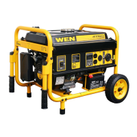
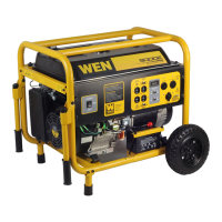
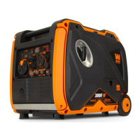
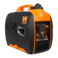
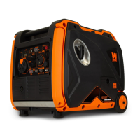
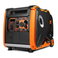
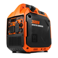
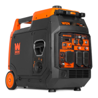
This document outlines the disassembly and reassembly process for a carburetor found in a Wen 5500 generator, specifically for models equipped with a 13 horsepower engine. The carburetor is a crucial component in internal combustion engines, responsible for mixing air and fuel in the correct proportions to create a combustible mixture that powers the engine. Its proper functioning is essential for the generator to start, run smoothly, and deliver consistent power output.
The manual provides a step-by-step guide, accompanied by illustrative images, to help users or technicians understand how to take apart and put back together the carburetor. This detailed approach is particularly useful for maintenance, cleaning, or repair tasks that might be necessary to ensure the generator's longevity and optimal performance. Over time, carburetors can accumulate deposits from fuel, experience wear and tear on internal components, or suffer from issues like clogged jets, all of which can impair engine function. Being able to disassemble and reassemble the unit allows for targeted troubleshooting and component replacement.
The initial steps of disassembly focus on removing external attachments. First, the two P2 (#2 PoziDrive) head screws that secure the solenoid to the bottom of the carburetor bowl must be removed. The solenoid is an electrically controlled valve that typically manages fuel flow, often acting as a fuel shut-off to prevent engine run-on or to control fuel delivery during starting. Following this, a 14mm hex head bolt located at the bottom of the carburetor bowl needs to be removed. These steps effectively detach the main fuel control mechanism and the primary fuel reservoir from the carburetor body.
Once these fasteners are removed, the carburetor bowl can be separated from the main body of the carburetor. The bowl serves as a reservoir for fuel, maintaining a consistent level of fuel for the engine. Inside the bowl, a float mechanism is typically found, which regulates the fuel level. The next step involves removing the pivot pin from the float, allowing the float to be pulled away from the carburetor. The float, often made of a lightweight material, rises and falls with the fuel level, actuating a needle valve to control the inflow of fuel into the bowl, thereby preventing overfilling.
Further disassembly involves accessing the internal components responsible for fuel metering. A ¼" flat head screwdriver is used to insert into the center stem of the carburetor to remove the jet. The jet is a precisely calibrated orifice that controls the amount of fuel entering the engine's air stream. Different jets are used to fine-tune the fuel-air mixture for various engine speeds and loads. After the jet is removed, the nozzle, which is located inside the center stem, can also be extracted. The nozzle works in conjunction with the jet to atomize the fuel as it enters the engine.
The document emphasizes that reassembly should be performed in reverse order of disassembly. This is a standard practice in mechanical repairs, ensuring that all components are put back in their correct positions and sequences. A critical detail highlighted for reassembly is to ensure that the o-ring is properly seated between the bowl and the bottom of the carburetor. O-rings are essential seals that prevent fuel leaks and maintain proper pressure within the carburetor system. A misplaced or damaged o-ring can lead to fuel leaks, air leaks, and ultimately, poor engine performance.
The manual also includes an exploded diagram of the 13 HP carburetor, which is an invaluable visual aid for understanding the relationship between the various components. This diagram labels key parts such as the fuel line, o-ring seal, float valve seat, main nozzle, float pivot pin, jet, float needle valve, float, lower bowl, 14mm bolt, and solenoid. Such a diagram helps users identify each part, understand its location, and visualize how they fit together, making both disassembly and reassembly much clearer.
In terms of usage features, the carburetor's function is to provide a consistent and correctly proportioned fuel-air mixture to the generator's engine. This ensures reliable starting, stable idling, and efficient power delivery under varying loads. A well-maintained carburetor contributes to fuel efficiency and reduces emissions.
For maintenance features, the document implicitly guides users on how to perform essential carburetor maintenance. Regular cleaning of the jets, nozzles, and fuel bowl can prevent common issues like clogging due to stale fuel or debris. Inspection of the float, float needle valve, and o-rings for wear or damage is also crucial. Replacing worn-out seals or damaged components, as guided by this manual, can restore the carburetor to its original operating condition, preventing costly repairs or premature engine failure. The ability to easily access and replace these parts makes the carburetor a serviceable component rather than a disposable one.
In summary, this document serves as a practical guide for maintaining and repairing the carburetor of a Wen 5500 generator. It breaks down a complex mechanical process into manageable steps, supported by visual aids, to empower users to perform necessary maintenance tasks. By understanding and following these instructions, users can ensure their generator's carburetor remains in optimal condition, contributing to the overall reliability and longevity of the generator.
| Fuel Type | Gasoline |
|---|---|
| Engine Type | OHV 4-stroke |
| Starting System | Recoil |
| AC Output | 120V/240V |
| DC Output | 12V/8.3A |