88
ASSEMBLY AND ADJUSTMENTS
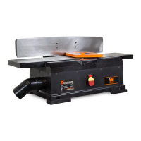
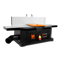
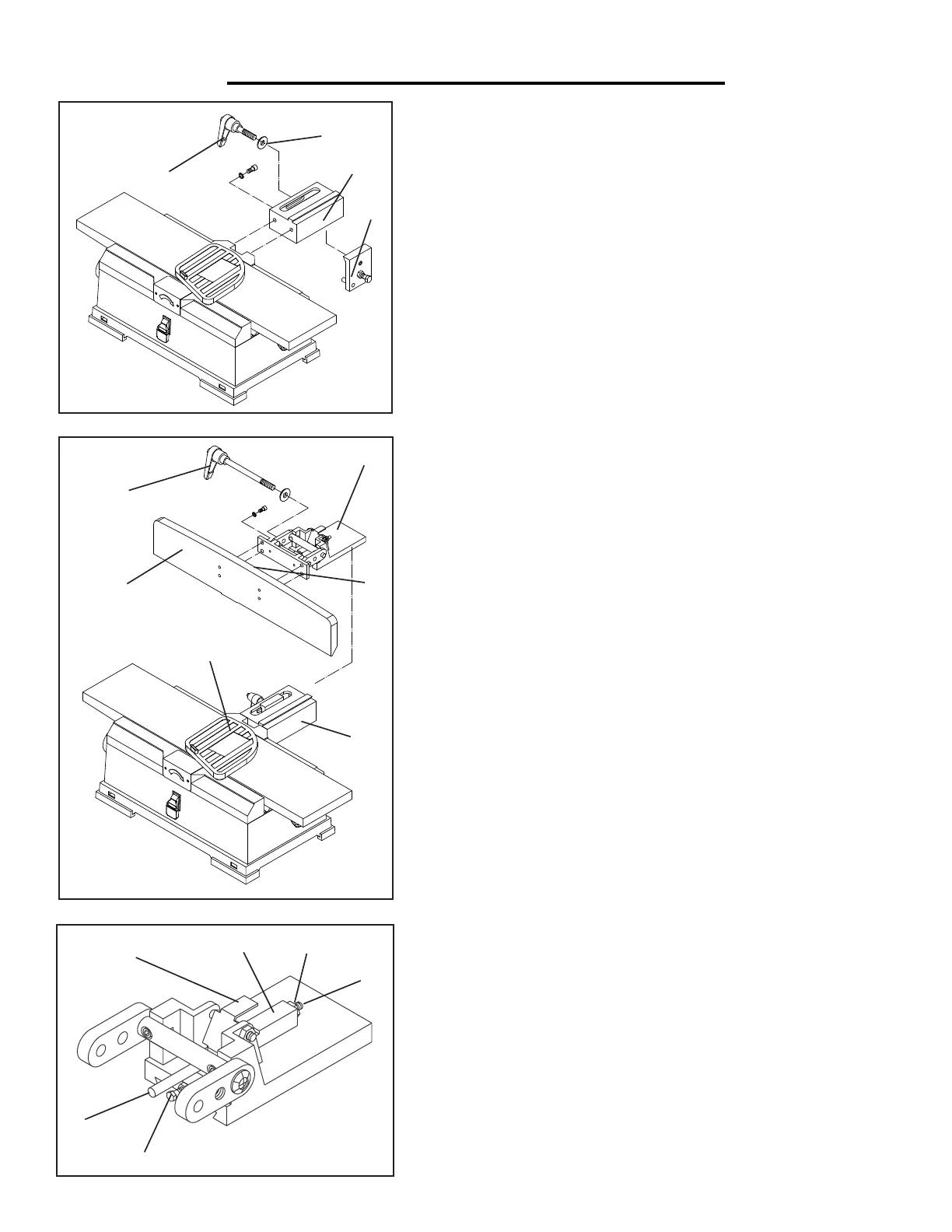
ATTACHING THE FENCE SUPPORT ASSEMBLY
1. Attach the fence support (Fig. A - 3) to the jointer with socket
head bolts and lock washers.
2. Insert the locking plate assembly (Fig. A - 4) into the support.
Position the plate so that pins are against the bottom edge of the
support.
3. Secure the plate in position with the fence sliding handle (Fig.
A - 1) and the spacer (Fig. A - 2).
INSTALLING THE FENCE AND FENCE BRACKET
1. Attach the fence (Fig. B - 3) to the fence bracket assembly (Fig.
B - 2) with four socket head bolts and lock washers.
2. Slide the fence and the bracket over and onto the dovetails of
the support (Fig. B - 4) and the locking plate (Fig. A - 4).
3. Continue to slide the fence forward so that the fence is over
the jointer’s table and the blade guard (Fig. B - 5) rests against the
fence. The entire width of the cutter head should still be covered
by the blade guard. Secure the bracket in position with the fence
sliding handle (Fig. A - 1).
4. Insert the fence tilting handle (Fig. B - 1) with a spacer through
the right link and thread through to the left link.
5. Make sure the limit plate (Fig. C - 3) is resting in the slot of the
block (Fig. C - 4). Position the fence against the shaft (Fig. C - 2)
and lock the fence in position with the fence tilting handle (Fig.
B - 1).
6. Place a combination square (not included) against the face of
the fence and the table surface. The fence and table must be at
a 90 degree angle to each other. If not, loosen the tilting handle
(Fig. B - 1) and the hex nut (Fig. C - 5) and turn the shaft (Fig. C
- 6) with a screw driver until the fence is square. Secure it back in
position by tightening the hex nut (Fig. C - 5).
7. Use a bevel gauge or a protractor to check the 45-degree in-
ward and outward limit stops. The 45-degree inward stop (Fig. C
- 1) is the hex head bolt located beneath the shaft. The 45-degree
outward stop (Fig. B - 6) is centered at the top of the backside of
the fence (Fig. B - 3). If adjustments are needed, loosen the hex
nut on either stop, turn the hex head bolt to the proper position
and secure in place again with the hex nut.
Fig. A
1
2
3
4
Fig. B
1
2
3
4
5
S
1fi
借(通)用件登记
爆炸图序号
机
种
旧底图总号
底图总号
签 字
日 期
区
Fig. C
1
2
3
4
5
6
6
 Loading...