WHEEL GUARD INSTALLATION (FIG. A)
WARNING: Use the wheel guard with disc grinding
wheels. Always close the latch to secure the guard.
Keep the guard between you and the wheel. Do not
direct guard opening toward your body.
1. The position of the guard can be adjusted to accommo-
date the operation being performed. To attach the wheel
guard, first disconnect the tool from its power supply.
2. Loosen the guard release/lock screw and position the
guard on to the spindle neck so that the bump on the guard
lines up between the notches on the spindle neck.
3. Rotate the guard in either direction to the desired posi-
tion. Fasten the screw (Fig A - 1) to secure the guard in
place.
7
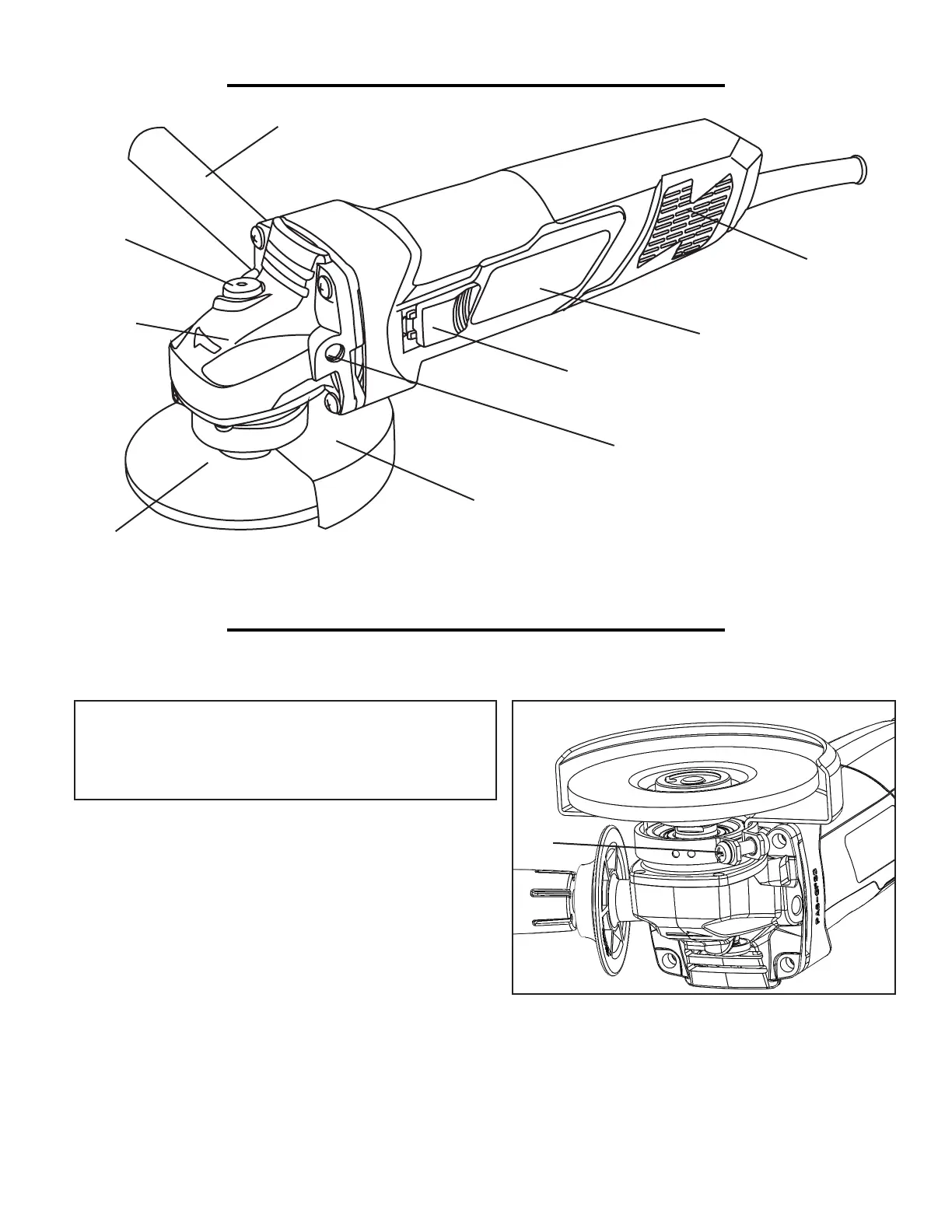
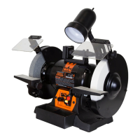
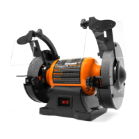
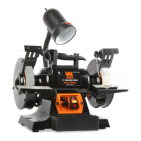
KNOW YOUR GRINDER
ASSEMBLY
ON/OFF Switch
Spindle
Lock
Handle Thread Holes
Side Handle
Gear
Box
Grinding
Disc
Wheel Guard
Motor Housing
Air
Vent
Fig. A
1