88
ASSEMBLY
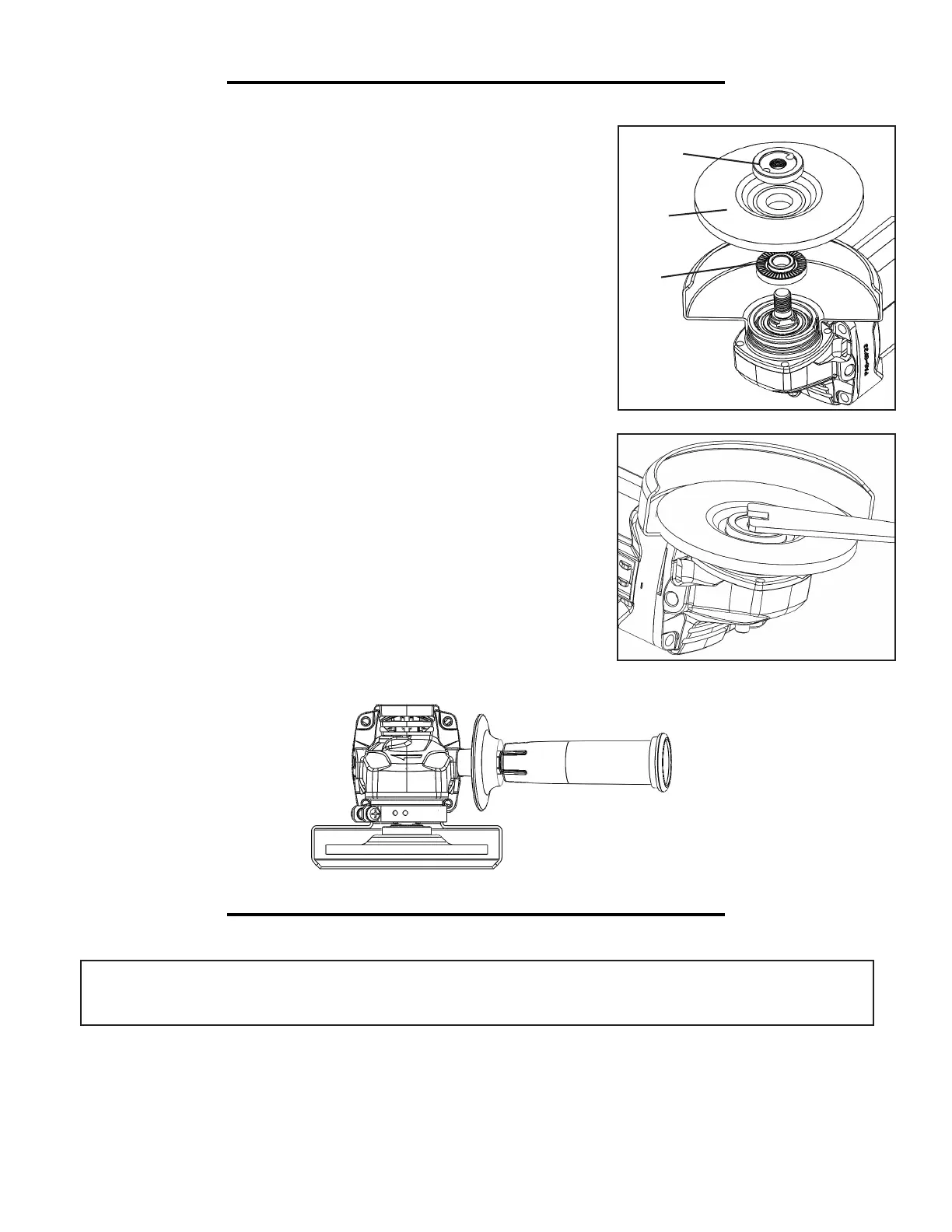
GRINDING DISC ASSEMBLY
1. Disconnect the tool from its power supply. Be sure that the wheel guard
has been properly installed before assembling the grinding disc.
2. Place the inner flange (Fig. B - 1) onto the spindle first so that the
grooves align with the spindle nut.
3. Next, slide the grinding disc (Fig. B - 2) onto the spindle.
4. Screw the outer flange (Fig. B - 3) into place with the protruding lip
facing downwards. This lip should fit snugly into the center of the grind-
ing wheel. Tighten the outer flange in place using the supplied lock nut
wrench (Fig. C) while pressing down the spindle lock to keep the spindle
from rotating.
OUTER FLANGE AND INNER FLANGE
Your tool is equipped with a threaded spindle for mounting accessories.
Always use the supplied outer and inner flange that have the same thread
size as that of the spindle.
REVERSIBLE SIDE HANDLE (FIG D)
The side handle used to guide and balance the tool can be threaded into
the front housing on either side of the tool. Use the side handle for safe
control and easier operation.
OPERATION
ON/OFF SWITCH (FIG. E - NEXT PAGE)
WARNING: DO NOT TURN THE ANGLE GRINDER ON OR OFF WHILE THE TOOL IS
UNDER LOAD; this will greatly decrease the life of the tool.
The tool is switched ON and OFF by the side switch located on the left-hand side of the switch. The tool features
a lock-on start switch which requires you to press the outermost tip of the switch to turn it off (Fig. E - 1).
Hold the tool with both hands since the torque from the motor can cause the grinder to twist. Start the angle
grinder before applying it to the workpiece. Let the disc come to full speed before contacting the workpiece. Lift
the tool from the workpiece before turning the machine off.
Fig. B
Fig. C
1
2
3
Fig. D