ASSEMBLY & ADJUSTMENTS
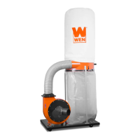
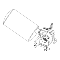
Mount the collector (C) onto the two poles in the front
as shown. Make sure that the side port of the collector
is facing the motor assembly to prepare it for hose con-
nection in Step 7. Secure them with M8x16 hex screws
and M8 washers.
5. ASSEMBLING THE COLLECTOR
Fig. 6
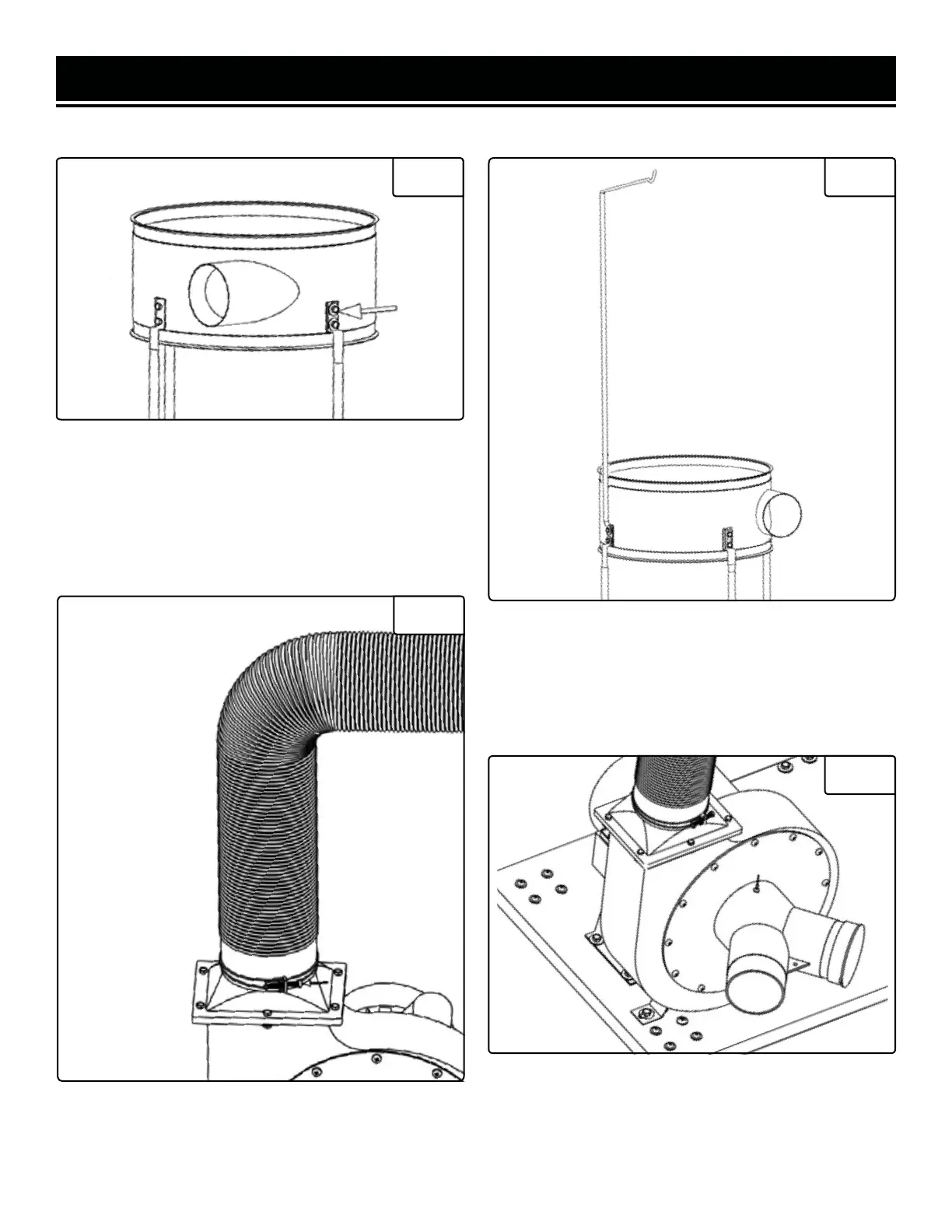
The upper bag support pole (E) will be installed in the
position overlapping the third bottom pole as shown.
Secure both poles onto the collector using M8x16 hex
screws and M8 washers.
6. INSTALL THE UPPER SUPPORT POLE
Fig. 7
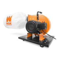
Attach one end of the hose (A) to the motor assembly
outlet and attach the other end to the collector outlet.
Secure the two ends of the hose with the hose clamps
(M) as shown.
7. CONNECTING THE HOSE
Fig. 8
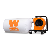
8. INSTALLING THE INLET CONNECTOR
Fig. 9
Attach the inlet connector (G) onto the inlet port of the
motor assembly. Align the hole on the connector with
the hole on the top of the inlet port and secure using a
cap screw.
10