6
1. Before assembling this product, make sure that
you have read and understand the information in
the box above.
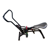
Press five 38mm Square Inner Caps (4) into the Base
(3) as shown.
Insert the two M8 x 45mm Bolts (1) up through the
indicated holes in the Base (3). Place a “U”-bracket
(2) on each Bolt and hand tighten the Bolts. Do not
fully tighten the Bolts yet. Make sure that the
indents on the Base are on the bottom and that
the “U”-brackets are oriented as shown in the
drawing.
1
Before beginning assembly
, read the following
information and instructions carefully.
•
Assembly requires two people.
• Place all parts in a cleared area and remove the
packing materials. Do not dispose of the packing
materials until assembly is completed.
• Tighten all parts as you assemble them, unless
instructed to do otherwise.
• For help identifying the small parts, use the
PART IDENTIFICATION CHART on page 5.
• As you assemble the weight bench, make sure all
parts are oriented as shown in the drawings.
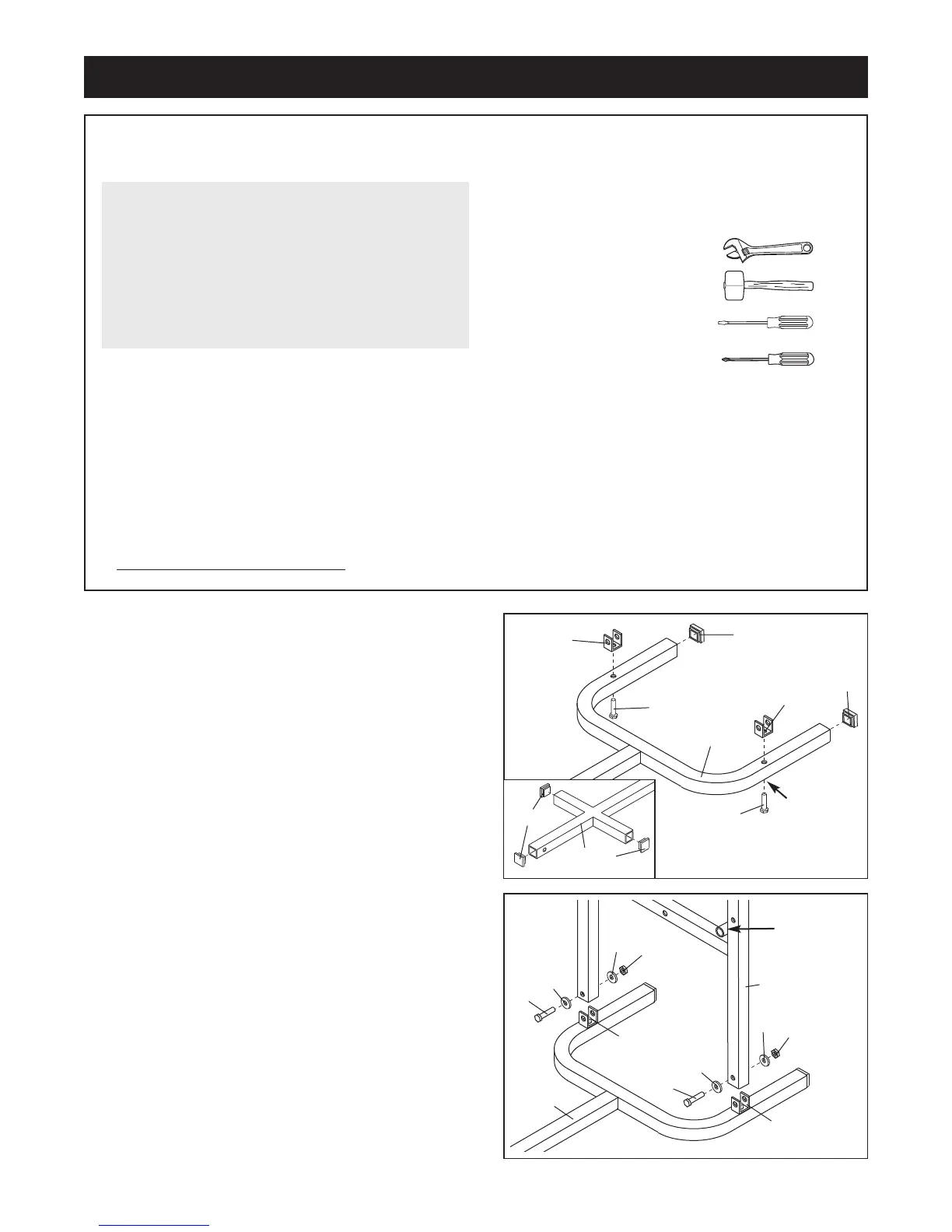
The following tools (not included) are required
for assembly:
• two adjustable spanners
• one rubber mallet
• one standard screwdriver
• one phillips screwdriver
•
lubricant, such as grease or petroleum jelly,
and soapy water
.
Assembly will be more convenient if you have the
following tools: A socket set, a set of open-end or
closed-end spanners or a set of ratchet spanners.
Assembly
Make Things Easier for Yourself
Everything in this manual is designed to ensure
that the weight bench can be assembled suc-
cessfully by anyone. Most people find that by
setting aside plenty of time, and by deciding to
make the task enjoyable, assembly will go
smoothly.
2
4
4
3
3
1
1
2
4
4
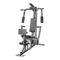
2. Place the “H”-frame (5) over the two “U”-brackets (2)
on the Base (3). Make sure that the “H”-frame is
oriented correctly. The indicated round tubes
must protrude on the side shown.
Attach the “H”-frame (5) to the “U”-brackets (2) with
two M8 x 52mm Bolts (6), four M8 Washers (23), and
two M8 Nylon Locknuts (7). Do not fully tighten the
Nylon Locknuts yet.
2
Protrusion
Indent
3
5
7
2
2
7
6
23
23
6
23
23