S.21
SA1
AND
SAO
MANUAL
CLUTCH
ADJUSTMENTS
With the transmission secured to the
engine,
replace
all water lines,
etc.
However, do
not
connect
the shifting linkage until all the
adjustments have
been
made and
are
satis-
factorily
tested~
Before securing the propeller
half
coupling to
the
gear
half
coupling, check to make
certain
that
the couplings do not run
out
more than
.002
inches
wi
th respect to
each
other.
Study
section IIAlignment to Engine
II
on Pages
14 and 15
of
Technical Manual.
The
transmission should
be
filled
with new oil
as
specified under lubrication.
The
transmission
can
be
parti ally adjusted
be-
fore the engine has
been
run. However, a
complete running test
is
necessary to
satisfact-
orily determine whether the adjustments have
been
properly made.
The
preliminary adjustments for the forward
drive
are.
made as follows: remove reverse
cover
plate,
rotate
pressure finger assembly
CI1d
screw
collar
(37) until lock screw
(42)
is up and facing
you.
Then, working
care-
fully to avoid dropping
either
screw or tools
into
clutch housing
--
Typical
Forward
Clutch
Adjust-
ment (SAl &
SAO)
I.
Back
out
the lockscrew
(42)
until the dog
on the end
of
the lockscrew
is
clear
of
the
hole in the pressure
plate
(35).
2.
Rotate the screw Collar (37) to the right
until the lockscrew
(42)
is
oPEosite the
next hole
in
the pressure
plate
(35).
3.
Tighten the lockscrew making certain
that
the dog on the end properly enters the hole
in
the pressure
plate.
4.
Continue this until a
decided
effort
is
re-
quired to shift into forward (approximately
26 foot pounds).
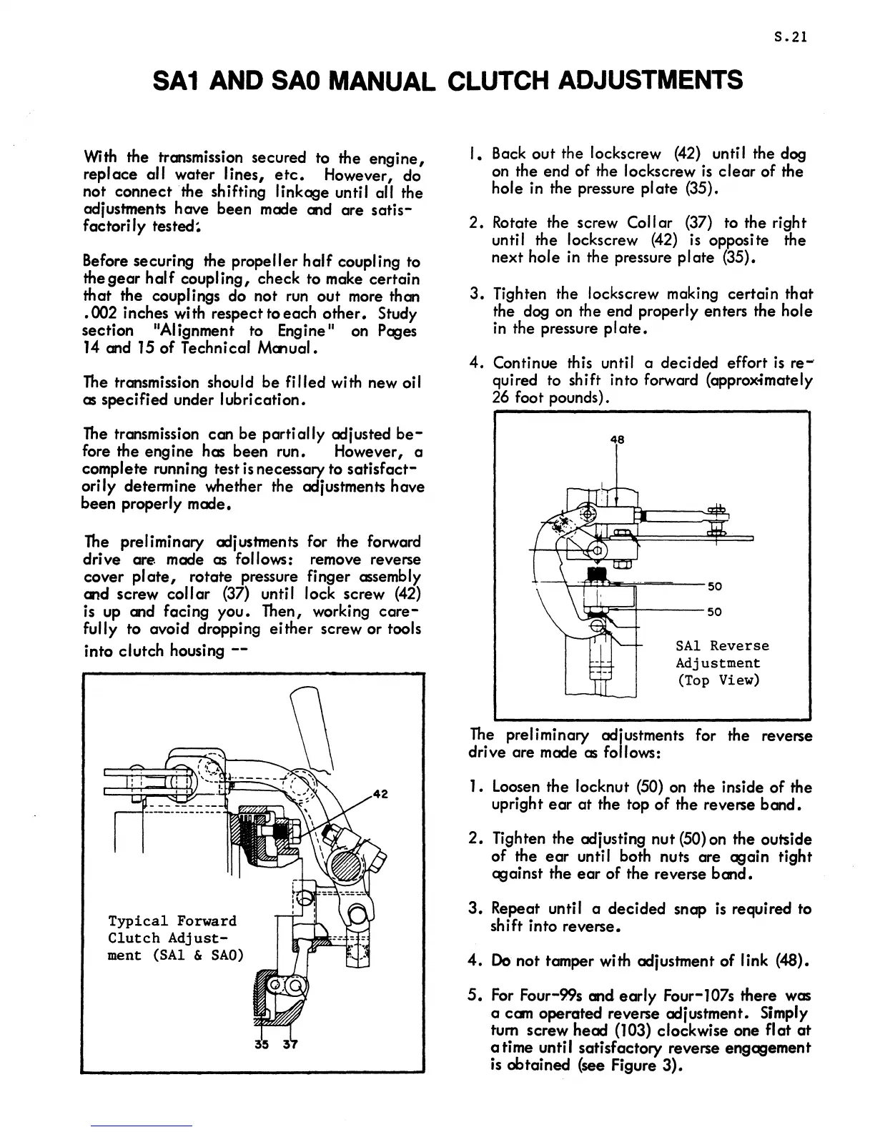
48
--~~O-~~----50
~n==4----
50
SAl
Reverse
Adjustment
(Top View)
The
preliminary adjustments for the reverse
drive are made
as
follows:
1.
Loosen the locknut (50) on the inside
of
the
upright
ear
at
the top
of
the reverse
band.
2.
TIghten the adjusting nut (50) on the outside
of
the
ear
unti I both nuts are again tight
against the
ear
of
the reverse
band.
3.
Repeat until a
decided
snap is required to
shift into reverse.
4.
Do
not
tamper with adjustment
of
link (48).
5.
For
Four-99s
and
early
Four-l07s there was
a cam operated reverse adjustment. Simply
tum screw
head
(103) clockwise one
flat
at
a time until satisfactory reverse engagement
is
obtained (see Figure
3).
 Loading...

